


Other Parts Discussed in Thread: DS560DF410,
DS560DF810 and DS560DF410 offer a variety of crosspoint and gearbox modes which can be used for 1:2 fanout, channel crossing, and NRZ/PAM4 modulation conversion. In this thread, I will cover 56G retimer crosspoint design, how to configure crosspoint/gearbox modes, and an explanation of each crosspoint/gearbox mode available.
Crosspoint Design:
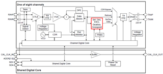
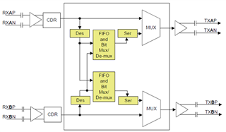
The channels of DS560DF810 and DS560DF410 are grouped into duals: ch0 and ch1, ch2 and ch3, ch4 and ch5 (DF810 only), and ch6 and ch7 (DF810 only) make up each dual. Each dual includes an integrated 2x2 crosspoint. The crosspoint exists within the Ser, Des, FIFO, Gearbox, Crosspoint functional block between the data slicers and the output multiplexer. This means signals are retimed before they pass through the crosspoint. When configuring any RX or CDR settings, note that they will be applied to the input signal on the associated channel. Any TX configurations will be applied to the output signal on the associated channel.
How to configure crosspoint/gearbox modes:
If you are using DS560 CAPI, there is a variable within the ChannelBringupParamStruct structure which can be used to configure the crosspoint/gearbox mode on each channel. Simply assign ChParam.ugearBoxCpMode to the corresponding mode before initializing the channel with InitChannel. If you need to change the crosspoint/gearbox mode after the channel is already initialized, there is a function available called cpGbConfiguration. Simply call this function with the corresponding retimer instance, channel number, and crosspoint/gearbox mode.
If you are not using DS560 CAPI, there are 2 macros which should be executed sequentially: Crosspoint Gearbox Module Initialization (opcode 0x41) and Crosspoint and Gearbox Configuration (opcode 0x40).
Crosspoint Gearbox Module Initialization:
- Opcode: 0x41
- Operand 1: Channel enable bitmap. Enable bit for each channel. (Offset: 0x00, Length: 1)
Crosspoint and Gearbox Configuration:
- Opcode: 0x40
- Operand 1: Channel enable bitmap. Enable bit for each channel. (Offset: 0x00, Length: 1)
- Operand 2: Mode. Options explained in below section. (Offset: 0x01, Length: 1)
Note that some crosspoint/gearbox modes (0x0, 0x1, 0xc, 0x80) can be configured on a single channel at a time. All remaining crosspoint/gearbox modes (0x2 -- 0xb) must be configured on both channels in a dual at the same time. This is done by enabling both channels in the channel enable bitmap operand when executing macros 0x41 and 0x40.
Crosspoint/gearbox modes available:
0x80: Analog Low Latency Path (default). This is the default straight mode which maps RX A – TX A and RX B – TX B. The signal travels directly from the data slicers functional block to the output multiplexer, bypassing the Ser, Des, FIFO, Gearbox, Crosspoint functional block. Bypassing this block has the advantage of faster input-to-output latency, which is typically 0.25 ns + 36 UI in analog low latency mode. All other crosspoint/gearbox modes route the signal through the Ser, Des, FIFO, Gearbox, Crosspoint function block, resulting in a typical input-to-output latency of 0.25 ns + 421 UI.
0x00: Straight Mode. This mode maps RX A – TX A and RX B – TX B similarly to analog low latency mode, however the signal is routed through the Ser, Des, FIFO, Gearbox, Crosspoint functional block. Straight mode is useful in applications which switch between straight and crosspoint modes because the input-to-output latency will remain consistent across device operation.
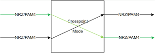
0x01: Crosspoint Mode. This mode implements channel crossover, mapping RX A – TX B and RX B – TX A.
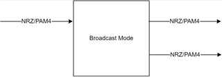
0x02: Broadcast from RX A. This mode implements fanout, mapping RX A to both TX A and TX B.
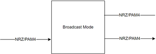
0x03: Broadcast from RX B. This mode implements fanout, mapping RX B to both TX A and TX B.
0x04: Gearbox MUX to TX A. This mode can be used to combine two retimed NRZ streams on RX A and RX B to one PAM4 stream on TX A. Both NRZ streams must have the same baud rate R (data rate R). The PAM4 stream will have baud rate R (data rate 2*R). No protocol and encoding functionality is supported. The mapping of the PAM4 output is programmable.
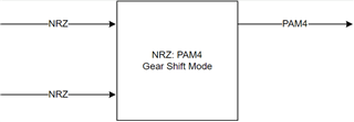
0x05: Gearbox MUX to TX B. This mode can be used to combine two retimed NRZ streams on RX A and RX B to one PAM4 stream on TX B. Both NRZ streams must have the same baud rate R (data rate R). The PAM4 stream will have baud rate R (data rate 2*R). No protocol and encoding functionality is supported. The mapping of the PAM4 output is programmable.
0x06: Gearbox DEMUX from RX A. This mode can be used to split a retimed PAM4 stream on RX A to two NRZ streams on TX A and TX B. The PAM4 stream will have baud rate R (data rate 2*R). Both NRZ streams will have baud rate R (data rate R). No protocol and encoding functionality is supported. The mapping for the PAM4 input is programmable. The mapping from MSB / LSB to TX channels A/B is programmable through an internal mux or through the PAM4 symbol mapping.
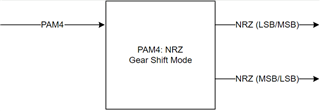
0x07: Gearbox DEMUX from RX B. This mode can be used to split a retimed PAM4 stream on RX B to two NRZ streams on TX A and TX B. The PAM4 stream will have baud rate R (data rate 2*R). Both NRZ streams will have baud rate R (data rate R). No protocol and encoding functionality is supported. The mapping for the PAM4 input is programmable. The mapping from MSB / LSB to TX channels A/B is programmable through an internal mux or through the PAM4 symbol mapping.
0x08: Up-Convert MUX to TX A. This mode can be used to combine two retimed NRZ (or optionally PAM4) streams on RX A and RX B to one NRZ (or PAM4) stream on TX A. Both input streams must have the same baud rate R/2. The output stream will have baud rate R. No protocol and encoding functionality is supported.
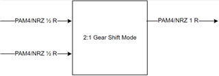
0x09: Up-Convert MUX to TX B. This mode can be used to combine two retimed NRZ (or optionally PAM4) streams on RX A and RX B to one NRZ (or PAM4) stream on TX B. Both input streams must have the same baud rate R/2. The output stream will have baud rate R. No protocol and encoding functionality is supported.
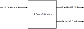
0x0A: Down-Convert DEMUX from RX A. This mode can be used to split a retimed NRZ (or optionally PAM4) stream on RX A to two NRZ (or PAM4) streams on TX A and TX B. The input stream will have baud rate R. Both output streams will have baud rate R/2. No protocol and encoding functionality is supported.
0x0B: Down-Convert DEMUX from RX B. This mode can be used to split a retimed NRZ (or optionally PAM4) stream on RX B to two NRZ (or PAM4) streams on TX A and TX B. The input stream will have baud rate R. Both output streams will have baud rate R/2. No protocol and encoding functionality is supported.
0x0C: GPIO Control of Crosspoint. This mode allows for switching between straight mode (0x00) and crosspoint mode (0x01) based on GPIO level.