This thread has been locked.

If you have a related question, please click the "Ask a related question" button in the top right corner. The newly created question will be automatically linked to this question.

AM26C31: Recommended differential line driver for external stepper motor controllers!

Part Number: AM26C31
Other Parts Discussed in Thread: AM26LV32E, THVD2450, THVD1450, AM26LV31E, THS6222, SN74LVC3G34, SN74LXC2T45, UCC27537

Hi All,

 First, I'm not sure if this is the right area to ask these questions, but here it goes. I am designing a higher-end motion control board and looking for a reliable, robust way to interface to external stepper motor controllers such as Stepper Online DM556T or TB6600 or any other external stepper motor driver with optoisolator inputs for pulse, direction, and enable and some have an alarm output. Can I use the AM26C31 device to send the necessary signals differentially, or is single-ended preferred? I want to use differential because of the outside noise and high voltage from a high voltage C02 laser power supply, AC noise, and other noise sources such as VFDs etc. 

My requirements are three differential outputs and one differential input on my board per axis up to nine axes of control. I am turned off by single-ended signals, especially at high step rates. If I go down the differential path, can I put the line termination resistors on the PCB, or do they REALLY have to be at the end of the transmission line? Since this is driving an optoisolator inside the external stepper motor driver, I want something easy for the customer to hook up. 

The maximum speed of the step pulse signals would be 0-1 MHz step frequency with a pulse width of 1-10 uS. Direction and enable signals aren't very fast. Max cable length is up to three feet (1 meter) maximum with twisted pair of 100 ohms.

What would you recommend I do? I also want the differential line drivers/receivers to be robust and have ESD protection. It would be great if you could share part numbers and example schematics.

Thanks,

Eric Norton

  • RS-422 drivers like the AM26C31 are designed to drive RS-422 receivers.

    If you use two wires for the anode and cathode of the optocoupler input, then the current flows like in a differential line, even if you drive one wire with a single-ended driver and connect the other one (at the driver's end) to VCC or GND.

    The optocoupler's LED affects the termination impedance. But for slow speeds, you do not need termination.

    In general, an antiparallel diode is enough ESD protection for an optocoupler input. (Both diodes clamp large voltages.) The driver can be protected with any appropriate ESD diode.

  • Do you have a recommendation for another part I can use for this particular application that would be better suited? I am exploring different ideas and trying to determine the best approach to this issue.

  • Hi Eric,

    AM26C31(TX) for the outputs and either THVD1450 or possibly THVD2450 for the (RX) are probably the best suited 5V supply devices for this type of application with the fewest number of IC's.  For 3.3V supplies AM26LV32E is a good device. 

    The most robust solution is probably using 4 THVD2450's (3 for TX and 1 for RX) - high common mode range, robust ESD protection (but honestly external ESD diodes will have the best ESD ratings - better than anything we integrate) and a high standoff voltage (which can be attractive in motor control applications). Obviously the downside is that its a 4-chip solution - but our quad devices are not the most robust. 

    Beyond that - since the bus is only a meter long you most likely can neglect termination completely (there will be a very small reflection produced at transition possibly as 1m is where faster devices like THVD2450 typically can have reflections at signal transition regardless of data-rate - but it should be pretty small at 1m) 

    In a lot of motor control applications though the choices generally are AM26C31(TX)/32(RX) for 5V systems and AM26LV31E/32E for 3.3V systems. 

    Please let me know if you have any other questions and I will see what I can do!

    Best,

    Parker Dodson

  • Hi Parker,

     My application is a board with three differential outputs (step, direction, and enable) with a differential alarm signal from the driver indicating an overcurrent or other issue per axis. The THVD series parts are bidirectional, not unidirectional, which I need here. I would also like the option to switch between 5v or 24v (I can install a jumper on the board to select this; I should have mentioned this in the original post) differential input/output. Is there a single part with three differential drivers and one receiver in a single package? I have looked high and low all over the internet and found a few parts from ic-Haus (iC-VX, for example, and others) with three differential outputs, which look ideal for this type of application. Still, I can't say for sure yet, and I just wondered if there is something TI has created that would do what I want. Is there something other than single-ended or differential that can drive high-speed opto isolators? Cost is also an issue, but I can bend a bit here if the solution is reliable and elegant. Please let me know.

    Thanks,

    Eric Norton

  • Hi Eric,

    I understand you only need unidirectional - the THVD devices I suggested have enables so you configure them to operate in a unidirectional manner (tie both DE and /RE to VCC for TX and DE and /RE to GND for RX). The reason being is that the 3 output and 1 input that you describe using our purely unidirectional parts would require 2 quad devices (for unidirectional differential transceivers we basically have quad channel devices only)

    That being said - we don't have a 3T 1R differential transceiver that would work - if you found a third party that has something that better meets your needs in an integrated solution then that may be the best way forward for your application - as all of our solutions will be multi-chip. That doesn't include the 24V option that you are seeking as well - I am not too sure what would work there besides maybe a wide supply differential line driver which is just another complexity to the system, but I am not sure the options there as the ones we use in certain applications will have a higher minimum supply than 5V. 

    Essentially - there most likely isn't something integrated that you can use from us that meets the goals of your applications as stated. What I presented in my first reply is the solution with the least amount of IC's based on your description (but will only work for 5V signaling  - if you need 24V signaling we'd generally need to see another line driver - it may be possible to use something like a THS6222 for attached to driver for 24V signaling and then bypass the driver when 5V is wanted - but that does add complexity to the system). So its possible to construct something that may work for your system from TI - but if you found a fully integrated solution and that is what is desired I don't think we have a great singular option here. 

    Please let me know if you have any other questions and I will see what I can do - but I think we may be at an impasse with your system requirements and what we offer, but please don't hesitate to reach out if you have any other questions!

    Best,

    Parker Dodson

  • Hi Parker,

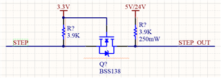
     I am beginning to think the differential path may be too complex. If I tell the customer the overall cable length should be a maximum of two feet, can I get away with single-ended ground-referenced signaling (send the signal with a ground wire in twisted pair), and would this be okay at up to 1 MHz? I would design the board in such a way that I would use something like this:

    This way, I have more freedom, and the cost is cut to a bare minimum. I have used this type of configuration for other circuitry on boards in the past, and the speed is pretty good. The level conversion aspect is nice, so that works. I am just a bit nervous that it won't be immune to outside noise, but if I use a shielded cable with multiple twisted pairs, that should work, right? Any thoughts and recommendations?

    Thanks,

    Eric Norton

  • This circuit has slow rising edges, on very little drive strength for high-level signals.

    Why do you need level conversion? What are the electrical characteristics of the inputs you're driving?

  • I am going from a 3.3V buffer output to a voltage-level translator to drive a 5V or 24V signal for stepper motor drivers such as STEPPER ONLINE DM556T. Inside the stepper motor drive is a 6N137 optoisolator with a selectable series resistor for 5V (170R) and 24V (3.3K) operation for STEP and DIRECTION inputs. 

  • Hi Eric,

    So I am a bit concerned with the drive strength of what you are showing on the level translator as the input impedance that you are looking at ranges from  much lower than the 3.9k to slightly lower than 3.9k so I am not confident that this level translation will work correctly with this specific load. Essentially my biggest concern here is lack of drive strength.

    Beyond that - a couple feet, depending on what is your single ended source consists of is possible - but it doesn't come without risk. Most of the motor communication/control applications that I have seen are short and generally use a differential setup still. Reason being, motors are noisy and they tend to have the potential of a lot of ground current  - which is why RS-422 or RS-485 is common in these types of applications (differential signaling more noise resistant and common mode voltage protection ranges are built-in RS-485 and RS-422 (but only RX is guaranteed in RS-422). 

    However using shielded cabling is beneficial - but the twisted pair really only works if the current is equal and opposite in both lines - if one is signal and one is ground and in these types of applications I_GND > I_Signal because I_GND usually consists of multiple parts, so I don't really know what kind of benefit you'd get out of this. If there was an EARTH connection the ground loop current can be reduced quite a lot with 2 resistors between GND and EARTH (around 100 ohms) this will limit loop current and then may be possible to get more benefit out of a twisted pair.

    Essentially:

    1. My main concern is lack of drive strength from level translator - I don't know if you will be able to source the correct current at the correct voltage based on the current design - so if single ended approaches are to be used the level translator must be able to source enough current. Essentially the level translator you are showing is good for high impedance inputs, but I wouldn't consider your perspective load high impedance. 

    2. You can use single ended wiring - but that comes with the fact that it will never be as noise resistant as a differential setup. You can use shielded cabling to help reduce impact + the short distance and relatively slow speed is also beneficial in this case. In general we don't see a lot of single ended signaling because the noise immunity benefits from differential are too high in noisier systems to ignore - but RS-232 for example is single ended and can be transmitted up to 15m (~50ft) at 1Mbps with some of our newer devices (drive strength would be too low for this application and it transmits positive and negative signal levels or I would have suggested RS-232). 

    Best,

    Parker Dodson

  • Hi Parker,

     The circuit is for illustration purposes only to convey my thoughts, and I would need to change the pullup resistors to allow for higher drive strength. The problem I see with this is that customers would use different stepper motor drivers, so that is an issue because who knows what series resistance or opto isolators are used in those drivers. I can't just select an arbitrary drive strength because not one size fits all. I could make the output programmable drive strength, which adds cost and complexity. Maybe I should return to the original idea of doing differential with adaptive drive strength. If the cable distance is short (two feet maximum), I wouldn't need the termination resistors, etc. Does this sound like a better plan of attack to go back to the differential driver idea and have a drive strength sensing or some way of detecting the required drive strength?

    Thanks,

    Eric Norton

  • RS-4xx drivers are designed to drive a standard termination resistor of about 120 Ω; they will not work with an optocoupler input that expects a voltage drop of 5 V with 15 mA. (There are devices that are designed to be driven with RS-422, but yours aren't.)

    The MOSFET-based level shifter will not work when you want to strongly drive a high level; the pull-up resistor would have to be extremly strong. But it can be used when you drive an inverted signal to the optocoupler's cathode, if the 3.3 V device has enough drive strength.

    I would recommend to simply use a strong 5 V buffer (e.g., SN74LVC3G34) or level shifter (e.g., SN74LXC2T45), and to use two wires (signal and GND when driving the anode, or signal and VCC when driving the cathode); the signals over these two wires are essentially differential, i.e., a noise induced into both wires with the same amount will not result in a change in the LED current.

    If you want to use 24 V, you can use gate drivers like the UCC27537 as level shifters.

  • Hi Clemens,

     Thank you very much for your explanation. I didn't think of doing a 5V buffer as, in my mind, it wasn't strong enough to drive the opto isolator, but now that you pointed this out, it makes complete sense to do it this way. I will go with the SN74LVC3G34 or a similar device. I use a Greenpak device to handle precise pulse delay and multiplexing and that also has the 3.3V to 5V level shifting built into it so I can run the 5V outputs directly into the SN74LVC3G34 and call it a day. Thanks for your help with this; much appreciated!!

    Thanks,

    Eric Norton

  • Hi Eric,

    I think Clemens answer is succinct and probably the best course of action for you in the simplest way. 

    Best,

    Parker Dodson

  • I agree, Parker. Thanks for your help as well Slight smile.

    Thanks,

    Eric Norton

  • Hi Eric,

    If you have any other questions please don't hesitate to reach out!

    Best,

    Parker Dodson

  • Hi Parker and Clemens,

     I do have one more question... To protect the output pin and be as robust as possible, can I use a BAT54 tied to 5V and ground and then follow it with a 100-ohm resistor? I also use these 0603ESDA-05N right on the output pin after the 100-ohm resistor to further suppress any potential ESD or overvoltage. I want the board to be as robust as possible and stand up to most issues a customer may try to throw at it. Let me know if I am on the right track or if you guys recommend something better.

    Thanks,

    Eric Norton

  • Sounds OK. But 100 Ω has a noticeable voltage drop; you will probably have to reduce it.

  • Hi Clemens,

     Okay, great. I have decided to remove the 100-ohm series resistor because, as you said, it does produce a considerable voltage drop. Since the optoisolator inside the stepper motor driver already has a series resistor to limit LED current, there is no need for one. Thanks for your help!

    Thanks,

    Eric Norton