This thread has been locked.

If you have a related question, please click the "Ask a related question" button in the top right corner. The newly created question will be automatically linked to this question.

SN65HVD72: 5 Meter Communication design

Part Number: SN65HVD72
Other Parts Discussed in Thread: THVD1419

Hi

I would like to use SN65HVD72 for an upcoming project, where we will have our main PCB, and the secondary PCB could be max 5 meters away. 

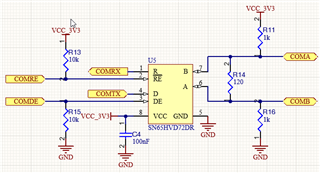
We would like simple UART communication between them, as the data rate does not need to be too fast, and the number of bytes is limited. We are thinking about using the following SN65HVD72 device. This is the circuit we aim to use on both PCBSs.

Is there anything additional we should do? How can we obtain samples of this part?

  • Hi Dharmesh,

    Checked Status(Good, Bad, Okay, ?) Additional comments
    Schematic pinout matches datasheet pinout Good
    Net names match schematic pinout Okay I see COMA connected to pin 'B' and COMB connected to pin 'A' this is okay since it's consistent with the other device but if you have other nets tied else where, you may want to double check A-A and B-B connections
    Local Decoupling caps on Vcc Good
    Termination Resistor present on transmission and receiver side  Good
    Digital Input pins are biased Good
    External Fail safe bias circuit Okay
    How can we obtain samples of this part?

    You should be able to put a request for samples for the device on the product page of the device.

    https://www.ti.com/product/SN65HVD72

    ^Click here and scroll down to ordering & quality

    For a newer device, you can also look at THVD1419 as a potential alternative.

    -Bobby

  • Thanks

    I will correct my schematic, in regard to the COMA and COMB label

    Is there a reccomnded method of testing the communication for this device or do we need to connect another device to see data samples

  • So when you send data through COMTX, if you enable the receiver (hold #RE LOW) then you can monitor COMRX. The data you send through Tx should match the data you receive on the Rx pin with some propagation delay. You can do this with a single board to verify everything looks okay before connecting to the cable. The second test I would do is connect the cable and then send data from one board to the other and verify the received data on the second board matches what was sent. You can also probe A-B on the receiver board and verify Math(A-B) looks okay (large enough voltage swings and fairly linear).

    -Bobby