A related question is a question created from another question. When the related question is created, it will be automatically linked to the original question.
If you have a related question, please click the "Ask a related question" button in the top right corner. The newly created question will be automatically linked to this question.
[FAQ] TMUXHS4212: When and how to AC coupling the passive MUX?
Many interfaces, such as PCIe, USB, DisplayPort, etc., require AC coupling between the transmitter and receiver. When using a passive MUX for these high speed interfaces such as the TMUXHS4212, a question always being asked is placement of the AC coupling capacitors.
A passive MUX has its own common mode voltage or Vcm requirement. For example. the TMUXHS4212 has a Vcm of 0 to 1.2V when the VCC is 1.8V or 0 to 1.8V when the VCC is 3.3V as shown below.
A device that is connected to a passive MUX will have its own Vcm, so it is important that the device Vcm needs to be within the passive MUX Vcm range in order to properly bias the passive MUX. If the device Vcm can not meet the passive MUX biasing voltage, then AC coupling capacitors are needed to remove the common mode voltage and an external biasing voltage is needed to properly bias the passive MUX.
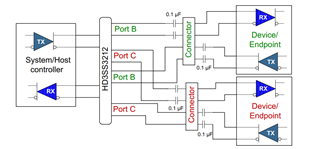
In the first example, with the connector provides an open connection to the outside world, there is no guarantee that Endpoint Vcm will meet the passive MUX Vcm requirement. The AC coupling capacitors are placed between the passive MUX and the Endpoint to remove the Endpoint common mode voltage. In this situation, the passive MUX is biased by the System/Host Controller assuming the System/Host Controller Vcm is within the passive MUX Vcm range. The AC coupling capacitance needs to follow the requirement of the particular interface and the value should match for the ±signal pair.
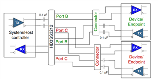
In the second example, the AC coupling capacitors are placed on the System/Host Controller transmit pair and Endpoint transmit pair. In this situation, the passive MUX on the top is biased by the Endpoint receiver and the passive MUX on the bottom is biased by the System/Host Controller receiver.
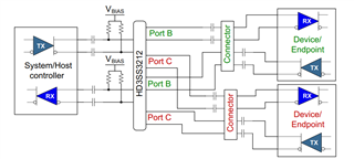
In the last example, both the System/Host Controller and Endpoint common mode voltage in the system is outside the passive MUX common mode voltage range. In this case, the AC coupling capacitors are placed on both sides of the passive MUX to remove the System/Host Controller and Endpoint common mode voltage. But an external termination network to Vbias is then needed. The Vbias must match the passive MUX Vcm requirement. The termination resistor depends on the particular system design application.