This thread has been locked.

If you have a related question, please click the "Ask a related question" button in the top right corner. The newly created question will be automatically linked to this question.

TPD6E004: ESD Diode selection

Part Number: TPD6E004
Other Parts Discussed in Thread: TPD4E004, TPD4S012

Hello Team,
We have a PCB with the MCU MSP432 and all the IO pins are taken to another board through a connector.
Both the boards are powered independently and all the IO pins are isolated.
Al  the signals are at 3.3V logic.
1). Where should we place the ESD diodes?
On the board containing MSP432 or the other board?.
2). We have SPI, UART, I2C, USB and CAN signals to the second PCB.
What kind of ESD Diodes do we need to use?. Unidirectional or bidirectional.
3) Can you please let us know the difference between the following?.
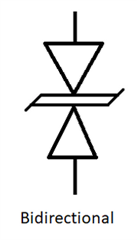
a).
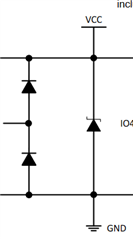
The above is a bidirectional diode
b).
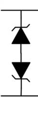
The above is a bidirectional but its anodes are connected together.
c).

The above is also a bidirectional but its cathodes are connected together.


In some ESD diode datasheets, I have seen some diodes with clamping voltage lower than working voltage. Why is that?.


Looking for your reply

  • Hi, 

    Please see answers below:

    1. For placement of ESD protection, it is recommended to place a protection diode as close to the connector or source of ESD as possible. In this case, since the IOs are on a different board, I would recommend placing the ESD diode on that board and not the MCU board. 

    2. SPI -> unidirectional, UART -> bidirectional, I2C -> unidirectional, USB -> unidirectional, CAN -> bidirectional. A few things to note, unidirectional is recommended when there are only positive voltages on the line and bidirectional is recommended when there are both positive and negative voltages. Bidirectional diodes can also be used instead of unidirectional diodes but not vice versa.

    3. a) This is actually not a bidirectional diode. This is a diode array that uses steering diodes. It is a common design for unidirectional diodes as well as multi-channel diodes. 

    b) This is a common anode bidirectional diode. This diode will have a lager forward drop compared to the diode shown in C. 

    c) This is common cathode bidirectional diode which tends to be the more common design. 

    4. The reason why some diodes will have a lower clamping voltage than working voltage is because they are deep snapback diodes. This is used for applications that have a operating voltage and abs max voltage that are very close. 

    Please let me know if you have additional questions.

    Best Regards,

    McKenzie 

  • Hello Team,
    Thank you for your reply.
    Sorry for replying late.
    Can you please look into the application note SLAU748B.
    They are using two types of ESD diodes.

    TPD4S012DRYR for USB line (connector U7) and TPD4E004DRYR for USB lines (connector USB101) and connector J102 and J11.
    Why are they using 2 types of ESD diodes for USB lines.
    Also, the signals TMS, TCK and all are unidirectional only, why we are using TPD4E004DRYR there.
    Some of our I2C and SPI lines are traveling to multiple IO boards.
    So do we need at add ESD diodes in each connector ends.
    Will this create any problem like capacitance issues.

    Looking for your reply.

  • Hi, 

    Yes, the application note was not done by us and was published a few years before I started at TI so I am not sure if we recommended any devices for the design or not. By the looks of it, they are using TPD4S012 on a micro-USB port and TPD4E004 for USB 101. If you want a more in depth look at ESD protection for USB Interfaces, check out this application note that we recently updated (SLVAF82).

    TPD4E004 is a unidirectional device which is most likely why it was picked for the TMS, TCK, and other lines. 

    For the question about placement for I2C and SPI, we recommend placing the diode as close to the source of ESD or to the connector as possible. 

    Best,

    McKenzie