This thread has been locked.

If you have a related question, please click the "Ask a related question" button in the top right corner. The newly created question will be automatically linked to this question.

DP83867IR: ETH PHYs: DP83867IRRGZT and DP83869HMRGZT - Magnetics

Part Number: DP83867IR
Other Parts Discussed in Thread: DP83869

We have used Ethernet PHYs DP83867IRRGZT and DP83869HMRGZT with processor AM6421BSFGHAALV. We followed reference design for AM64xx and used same PHYs as reference.

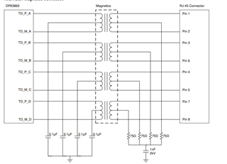
We have used below RJ45 connector with inbuilt magnetics.

MFR# 2250731-1 from Bel Fuse Inc.

MFR# 0826-1K1T-43-F from Bel Fuse Inc

But internal design of magnetics is different than what is used in AM64xx reference design.

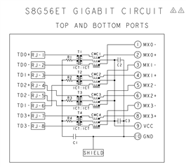
For AM64xx reference design, below are RJ45 connector with inbuilt magnetics.

MFR# LPJG17512AONL from Link-PP

MFR# LPJG16314A4NL from Link-PP

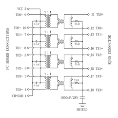
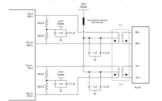
I have attached datasheets of all 4 connectors.

I tried to find application note or any article that can explain different types of magnetics, but I did not find any specific information.

Can you please help to resolve below queries:

1) I used RJ45 with different magnetics design than reference design. Does this make any difference?

2) What are different types of ethernet magnetics and how does it make any difference to ethernet interface? Is there any application note available?

3) What are applications of different type of ethernet magnetics?

Regards,

Nikhil Jadhav

8535.LPJG17512AONL.pdf

2350.LPJG16314A4NL.pdf

2350.2250731-1.pdf

5074.0826-1K1T-43-F.pdf

  • Hi Nikhil,

    These are excellent questions. First, let me go over what we recommend for Magnetics in the DP83867 & DP83869. Both of these PHYs are gigabit capable and require 4 differential pairs. In the data sheet we give the example circuit below (see Figure 1). Note that each pair/channel of the transformer (outlined labeled Magnetics) has the center tap connected to a 0.1uF capacitor to ground. For a direct comparison, see 2250731-1 from Bel Fuse Inc.'s schematic (figure 2). The RJ-45 (connector side) is on the left of this schematic (opposite of Figure 1). Here, only two channels have a capacitor, with all channels shorted together. We have seen this place a role in causing compliance issues.

    The next thing worth pointing out is that a few of the connectors you sent have a VCC connection to the center taps (see Figure 3). The output of the PHY's usually come in two flavors: Voltage Mode or Current Mode. Our DP83822 (100Mbps, not gigabit) is an example of a current mode PHY (see Figure 4). For this kind of PHY, we want the center tap to be pulled high.

    The DP83867 & DP83869 are voltage mode driven and do not require a pull up. VCC can be left floating.

    Our data sheets have the Magnetic Isolation Requirements for each PHY and the following FAQ will help determine if your chosen magnetic meets the requirements.

    [FAQ] How do I choose magnetics for my industrial PHY?

    Figure 1 - Recommended Magnetics Connection

    Figure 2 - 2250731-1 from Bel Fuse Inc. Schematic

    Figure 3 - LPJG16314A4NL from Link-PP Schematic

    Figure 4 - DP83822 Recommended Magnetic Connection