


When signal goes through two different transmission line, signal may get reflected based on difference between these two medias impedances. Return loss is the ratio of the reflected signal to the launched signal. If signal goes through with no reflection then we have minus infinite dB return loss. On the other hand, if all of the signal gets reflected, we have 0dB return loss.
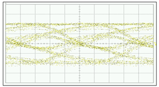
If we have poor return loss signal across its frequency bandwidth is not going through. Below is an eye diagram with poor return loss. Eye diagram is distorted since frequency components of the signal were not transmitted due to the poor return loss.
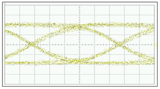
On the other hand the same signal with good return loss allows signal and its harmonics to pass through the media has the following eye diagram:
Therefor it is important to closely match impedance whenever we go from one transmission media to another. Below are some general guidelines:
1). Contact connector or cable vendor to get optimized anti-pad or pcb layout for the connector you are using. Connector anti-pad impedance should match transmission line impedance leading to this connector.
2). PCB lay out simulation is advised to make sure target impedance is maintained and we reduce parasitic of different components or passive components through the signal path.
3). Reduce trace length to minimize negative side effects due to the adjacent trace or components.
4). Use VNA and TDR to analyze impedance discontinuity. Use this knowledge for your next PCB design.
5). Use parts with extra return loss margin to compensate for return loss degradation
6). Provide void under high speed pads to reduce parasitic effects
Regards, Nasser