This thread has been locked.

If you have a related question, please click the "Ask a related question" button in the top right corner. The newly created question will be automatically linked to this question.

THVD8000: VCC and TTL level confirm

Part Number: THVD8000

Hi team,

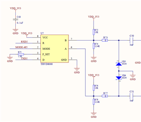
 my customer target to use 3V3 MCU to communicate with THVD8000, but we are seeing the Vod parameter is under 5VCC level and then it can get enough Vod magnitude.

meanwhile ,the VIH >2V is okay for 3V3 MCU, but VOH =VCC – 0.4 ,if power by 5VCC, then the VOH = 4.6V and >3v3MCU abs.

so can you help to comment how to use 3V3MCU to connect with THVD8000? or does the 3V3 power supply for THVD8000 is still okay ?

  • Hi Allen,

    You can use 3.3V supply for this device - the typical characteristics in the datasheet only refer to 5V, but the min/max conditions are for device across operational range - so the device doesn't perform as well at 3.3V because there will be less drive strength (the driver output is directly sourced from VCC - so lower VCC means lower VOD - but the device will still output at least 1.5V across 54 ohms even at a 3.3V supply). 

    There is no termination resistor shown in the diagram above and for the THVD8000 it really isn't a suggestion - you need a termination (120 ohms) on the start and end nodes because the transition time on this device is fast regardless of what modulation frequency or data rate is being used so reflections at signal transitions are possible at very short lengths. 

    Please let me know if you have any other questions. 

    Best,

    Parker Dodson

  • Hi Parker,

     tks the support here. we will keep using 3V3 in this case.

    And also tks for the supplement of the termination resistor, already ask customer to add it.

  • Hi Parker,

     we decide to use 3V3 MCU but 5V for THVD8000 at 5V, Here is the update SCH:

  • Hi Allen,

    Parker is out of office currently. 

    I see that you changed the R net for the device to be a resistor divider to output ~3.3V. 

    What's the fastest data rate are you trying to receive? The resistor divider's output can kinda of get attenuated further with frequency if the resistors are too weak (it acts like an RC circuit). You may need to modify it further if you are trying to operate at higher speeds.

    -Bobby

  • Hi Bobby,

     tks for the comments,  customer use 1.5k R for F_SET Pin, so it is 500kbps for UART and 5M for carrier speed,

     any solution can help us working on such highest speed with 5V for thvd8000 and 3V3 MCU.

  • Hi Allen,

    I threw the RC circuit in a simulator just as a sanity check to make sure the resistors selected would be able to switch at 1Mbps (2x your rate). I assumed a parasitic capacitance of 50pF (some from PCB trace and MCU input) then assumed 200 ohm Ron of the Rout. The signal output was able to swing to Vcc and GND in time for worst case situation. 

    So no concerns on the level shifter resistor values.

    Sorry, one last question. What is the max distance you are trying to support? This will affect how fast you can potentially communicate at.

    -Bobby

  • Hi Bobby,

     tks for the checking here!

    customer target to use 4node with 160meters.

  • Based on this, the speed you're operating (sending) through the differential line is actually 5Mbps so it looks like 160 meters is kind of far for this speed based on the graph. You may see jitter of about 3% based on this which should still work. 

    -Bobby