This thread has been locked.

If you have a related question, please click the "Ask a related question" button in the top right corner. The newly created question will be automatically linked to this question.

TLIN1021A-Q1: LIN output rise/fall time

Part Number: TLIN1021A-Q1

Hello team

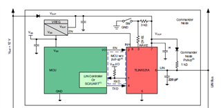
I have implemented LIN using the recommended circuit configuration, but I have one question regarding the rise time of LIN.
The LIN output line consists of a 1kΩ resistor and a 220pF capacitor, and I think the rise time will be about MAX2us.
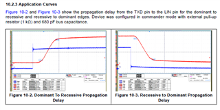
However, when measured, the rise time is about 7 us, and the data sheet "10.2.3 Application Curves" also shows a rise time of about 7 us, just like the actual measurement.

Why does it take 7us for the waveform to rise?

  • Rui,

    LIN signals are regulated to meet duty cycle and emissions requirements for automotive systems. This requires tailoring both the falling edge and the rising edge of the signal to ensure that these limits are met. LIN transceivers are not simply open-drain drivers, but are single-ended transceivers that can shape an output signal to meet LIN requirements.

    There is more information about the requirements of the LIN physical layer in ISO 17987-4 and SAE J2602-1 which give specifics about these parameters. Many of these parameters are shown in the specification tables for our LIN transceivers including TLIN1021A-Q1.

    Best,

    Danny