This thread has been locked.

If you have a related question, please click the "Ask a related question" button in the top right corner. The newly created question will be automatically linked to this question.

DP83TC814S-Q1: Abuot the POWER-UP TIMING Issue

Part Number: DP83TC814S-Q1

Tool/software:

Hello TI Team,

From the datasheet, 

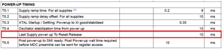
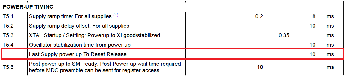
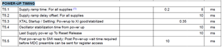
1).  T5.1 Supply ramp time: For all supplies

Q:  Does VDDIO and VDDMAC also have the same requirement?

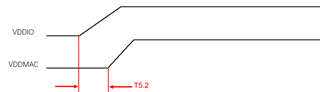
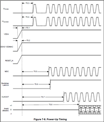
2). T5.2 Supply ramp delay offset: For all supplies

Q:  I can't understand this item. It seems same with T5.1 from Figure 7-8. Could you explain more clearly?

Best Regards!

  • Hello Jingkun,

    Q1: Yes this applies to all power supplies for the PHY including VDDIO and VDDMAC.

    Q2: T5.1 is the timing requirements of ramp up for all supplies. T5.2 is the supply ramp delay offset between VDDIO and VDDA that is to be at a max of 10ms. 

    Regards,
    Avtar

  • Hello Avtar,

    Q1: T5.1 Supply ramp time:  does the raise time test from 10% to 90%  or 20% to 80% or 0V to 3.3V or other test condition?

    Q2: T5.2 Supply ramp delay offset: I can't clear understand datasheet show the POWER UP Timing figure. 

           Below is my understand, is it right?  If it is incorrect,  please show me the detail example waveform

    Q3: Which signal is "Bootstrap Latch-in"? 

           How to measure the time of T5.6?

    Best Regards!

  • Hello Jingkun, 

    Q1: Time for power supplies to go from 0V to the voltage level needed from the supply (3.3V or 1.8V).

    Q2: Yes, your understanding is correct but the difference is between VDDIO and VDDA.

    Q3: The Signal for bootstrap latch in is any of the HW bootstrap pins the customer wants to configure. How to measure would be the time between initial power up ramping to the time the bootstrap latches into a mode. 

    Regards,

    Avtar

  • Hello Avtar,

    Q4: About the "Last Supply power up To Reset Release" of Power Up Timing:

    I can't clearly understand the requirement. Could you have a check?

    Does it require as below waveform?  If it is right, is there no minimum reset time requirement for IC(RESET_N keeps low time)?

    Best Regards!

  • Hello Jingkun,

    The T5.4 number is the time after power supply ramp, that the internal POR (power on reset) is released.

    Regards,

    Avtar

  • Hello Avtar,

    As your mean, it is decided by the IC internal POR. We don't need to care the time. Is it right?

    We only need to care below Hardware RESET_N:

    Best Regards!

  • Hello Jingkun,

    Both you need to care about internal power on reset and hardware reset as both have different functions however I believe your question on what is more pertinent then you maybe correct hardware reset line has a direct impact on PHY function. 

    Both you should take into account for, make sure timing requirements are met on internal POR and hardware reset.

    Regards,
    Avtar

  • Hello Avtar,

    As your reply, the timing is the internal POR (power on reset) release time.

    We don't know how to measure the time.

    Could you give us some suggestion?

    Best Regards!

  • Hello Jingkun,

    That line is related to the line above it which is the time it takes for oscillator to stabilize after power up. You will be able to measure that time and make sure the timing meets requirements. In terms of the highlighted line, I apologize I was mistaken in that both need to be taken in account for. For hardware reset you can measure on the RESET pin, however for the highlighted line the oscillator stabilization time should be measured instead. 

    Regards,

    Avtar