This thread has been locked.

If you have a related question, please click the "Ask a related question" button in the top right corner. The newly created question will be automatically linked to this question.

DP83848K: SQ/NOPB

Part Number: DP83848K

Tool/software:

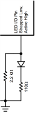
When LED_SPEED pins drive the RJ45 green LED, 100M is green and 10M is not on, the probability is 0.2%, the rest are 100M is not on, 10M is on, both cases are able to communicate normally. The schematic diagram is also shown below, in which the pull-down resistance is 270Ω, and the LED_SPEED pin voltage is 1.8V when AN1 is powered on and started, it is judged to be low, if the LED_SPEED pin is 1.75V, the LED_SPEED pin is judged to be a high level 3.3V output, the voltage difference between the two is so small. Will it also be at the critical value? What is the architecture of the LED driver inside the chip that can cause such a strange problem??

  • Hi Jiong,

    I will discuss with the team and provide you an response tomorrow.

    --

    Regards,

    Hillman Lin

  • HI Jiong,

    If possible, could we check the test condition that you are seeing this scenario.

    • What temperature are you seeing this behavior? Room temperature?
    • May I ask for the schematic on the LED structure around the LED pins and inside the RJ45 connector?
    • If possible, could you also probe the LED1 voltage level during strapping or power up phase. We want to make sure the strapping voltage level satisfy the datasheet spec.

    --

    Regards,

    Hillman Lin

  • 1,Room temperature 25℃

    2,As follows:

    3,the LED1 voltage level during strapping or power up phase is1.8V,However, a little below 1.8V and similar to 1.75V May cause problems。

  • Hi Jiong,

    May I ask what is the VDDIO level for your PHY? Is it 3.3V? 

    If so, the voltage strapping voltage on the LED pins is lower then the specification. VIH of the this PHY should be around 2V.

    If possible, could you make sure voltage during the strapping phase is 2V to make sure the PHY is strap into the correct stage?

    --

    Regards,

    Hillman Lin

  • Hi Hillman

    1,Yes, it's 3.3V

    2,VIH of the this PHY should be around 2V.The current of the LED will be affected at 2V. Under the case of 1.8V LED_SPEED, different lighting modes will appear at 100M speed. I would like to know what the internal logic of this pin is, can you explain it?

    3,There is also a problem is that at the same 100M rate, in the case of continuous power to reload the PHY driver, the LED lighting mode is the opposite, continuous power theoretically should not judge the high and low levels, which can explain?

  • Hi Joing,

    If possible, could you provide a register dump on 0x0000 to 0x001F when customer see this issue?

    We want to make sure the PHY is strap correctly during this stage?

    --

    Thank you,

    Hillman Lin

  • Hi Hillman,

    1,Register configuration is as follows:

    2,Whether the level of the IO pin can be changed by the underlying drive threshold, such as 2V to 1.5V???

    dp83848寄存器配置.txt
    0x00 3100
    0x01 786d
    0x02 2000
    0x03 5c90
    0x04 01e1
    0x05 cde1
    0x06 000f
    0x07 2801
    0x10 4015
    0x14 0000
    0x15 0800
    0x16 0100
    0x17 0021
    0x18 0000
    0x19 8001
    0x1A 0904
    0x1B 0000
    0x1C 0000
    0x1D 6011

  • Hi Jiong,

    Thank you for sharing the information.

    There might be a possibility that underlying driver threshold effect IO pin stage of the LED driver.

    --

    Regards,

    Hillman Lin

  • Hi Hillman,

    1,Can I ask whether the threshold of 2V input voltage of LED pin can be reduced by modifying the underlying drive to reduce the judgment level? For example, if the voltage can be reduced to 1.5V, it is considered to be a high level, and whether we will inform it through our FAE?
    2,There is also a problem, whether the status of the LED is determined to follow the RESET pin, not only when it is powered on.

  • Hi Jiong,

    One more thing I would like to confirm.

    From schematic, can I see where is the LED connected to on the schematic? Is it connected to some load or SoC?

    I check it with the team, the output voltage of the LED voltage should not change. If the LED is connected to some other GPIO, it might change the polarity of the LED. We would like to check it on schematic.

    --

    Regards,

    Hillman Lin