This thread has been locked.

If you have a related question, please click the "Ask a related question" button in the top right corner. The newly created question will be automatically linked to this question.

MAX3221E: How to connect C3 in application

Part Number: MAX3221E
Other Parts Discussed in Thread: MAX202, TRS202E

Tool/software:

Hi team,

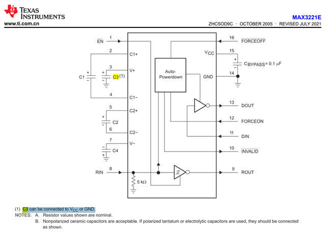
In our datasheet, C3 can be connected to GND or VCC. While in competitor ADM202E datasheet, ADI require C3 connected to Vcc. And I didn't see internal block diagram in our DS. Could you please kindly help on below questions:

  1. Why C3 can be connected to GND or VCC?
  2. Help share internal connection to help us understand question 1.
  3. Can customer replace ADM202E by MAX3221E directly with C3 connected to Vcc?

B R,

Owen

  • V+ is the output voltage of the charge pump. As a switching supply, it needs a capacitor to reduce ripple.

    C3 can be connected to any stable voltage. Both GND and VCC are stable; you could also use any other supply voltage between them. The only difference is the voltage over C3.

    The ADM202E is likely to work with C3 connected to GND. Anyway, the MAX allows connection to VCC, so it will work.

    The ADM202E and MAX3221E have different pinouts; the MAX202/TRS202E would be P2P replacements.

  • Hi Owen,

    Clemens is correct.

    Why C3 can be connected to GND or VCC?

    The C3 capacitor only needs to be connected to a reference voltage that doesn't move. The switching regulator before the V+ node will try to regulator the voltage to the VoH level that is spec'd in the datasheet. C3 is there to hold the charge generated by the switching regulator.

    Help share internal connection to help us understand question 1.

    https://www.ti.com/lit/ta/sszt674/sszt674.pdf?ts=1717452989348&ref_url=https%253A%252F%252Fwww.ti.com%252Fdocument-viewer%252Flit%252Fhtml%252FSSZT674

    This is an app note that walks through how charge pump regulators work on a high level.

    I used figure 1 to make an IBIS experiment from:

    You can see in this one, the cap (what you would call C3) is tied to GND and the Vplus voltage swings to about 5.9V

    Same circuit but the capacitor on Vplus is now tied to Vcc:

    You can see this one also basically swings up to 5.9V

    This kind of gives you an idea on how this works. The minor dips you see I think are from the switches not fully turning off on time, in the real RS232 charge pump circuit, you shouldn't see this. So again think of this as a high level view of how the circuit works.

    Can customer replace ADM202E by MAX3221E directly with C3 connected to Vcc?

    As Clemen's mentioned, these aren't pin to pin. Look to TRS202E.

    -Bobby