


Tool/software:
Hoping to get get some guidance on correct grounding for a CAN Bus I have designed. The following diagram gives a high level overview of the system connectivity:
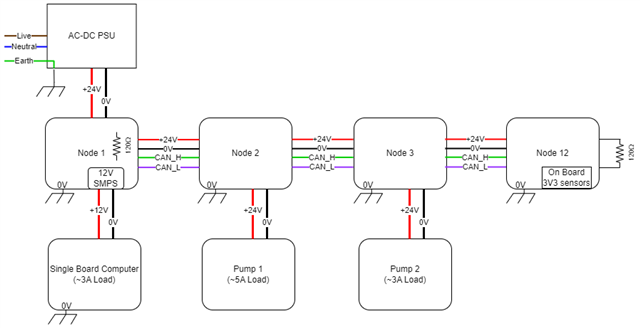
Some notes on the setup:
- There are a total of 12 nodes, I've only drawn 4 in the interest of repetition.
- Each node is a custom designed PCB.
- Each node has an onboard DC-DC SMPS which powers the MCU, CAN transceiver and applicable on-board peripherals. These all share the same common ground (labelled 0V) in the diagram.
- CAN_H and CAN_L are twisted pair.
- CAN reference (CAN_GND) is the 0V system ground.
- Each node has mounting holes tied to 0V net, which directly tie the PCB to the chassis, indicated by the chassis ground on each node.
- Single Board Computer has its ground reference tied to the chassis.
- Pump 1 and Pump 2 are simply turned on/off via a MOSFET.
I believe this may be creating a ground loop as I am connecting 0V between each node via the power cable as well as connecting each nodes 0V net to the chassis.
I am seeing quite a clean CAN signal when running on the bench (with no chassis connection). Inside the chassis, there's a significant amount of extra noise visible on the signals.
I'm looking for guidance on best practice on how I should be running both the CAN reference as well as how the nodes should be tied to the chassis. I.e. should all the nodes and devices powered by those nodes all be connected to the chassis?
Thanks in advance!
