This thread has been locked.
If you have a related question, please click the "Ask a related question" button in the top right corner. The newly created question will be automatically linked to this question.
Tool/software:
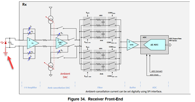
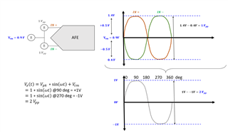
Since our photodiode is in a single-ended input configuration, would the AM26LV31E be suitable for converting the photodiode into a differential signal to serve as the input of the AFE4400? Thank you.
No, it has digital inputs that expect valid logic voltage levels.
You should use photodiodes that can be floating.
Hi Ven,
Thank you for your question. The AFE is looking for an analog input to the device. I am not an expert on the AFE4400, but I believe that you would want to use a balun to convert a single-ended to differential signal. Mini Circuits has several options to choose from, depending on your input frequency: RF Transformers and Baluns (minicircuits.com)
The main thing to consider here is the input full-scale range of the device. Because the TIA has a full-scale range of ±1 V, TI recommends that the input to the ADC does not exceed ±1 V, which is approximately 80% of its full-scale (datasheet pg. 74)
I have also drawn you a diagram for this situation. It is helpful to understand this diagram along with the diagram in the AFE4400 datasheet on pg. 72. Notice that the AFE4400 datasheet mentions a Vcm = 0.9 V (datasheet pg. 9, “Common-mode voltage on input pins”). This means that the differential signal IN+ / IN- will swing around 0.9V. I understand the ±1 V to be a maximum swing of 2 Vpp, so each differential leg has an allowable swing of 1 Vpp. Here is another helpful reference to understand this: (+) [FAQ] ADS5263: Differential input voltage swing vs single-ended signal pk-pk voltage.
I also found this to be a helpful resource (question 11): (+) AFE4400 / AFE4490 / AFE4403 / AFE4404 FAQs
Regards, Amy