THVD1400: Layout Review: RC Filter for UART inputs on MCU

Part Number: THVD1400
Other Parts Discussed in Thread: ESDS452, ESDS552, TSD05

Tool/software:

Hello E2E Community,

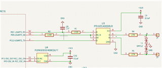
We are using THVD1400 for our RS485 use case with a maximum data rate of 20kbps. The maximum trace lengths on the PCB from THVD to MCU are less than 6cm.

I would like to confirm from your expert review if we can continue using following configuration for our end product, especially:

  1. RC Filter at Rx: The MCU Errata has suggested to add a heavy RC Filter - is a capacitance of 10nF okay with R of 120Ohm in this RC configuration?
  2. Series resistor of 120R on the DE trace for added noise immunity
  3. No resistor on the Tx line (Do we need to add any series resistor here to dampening?)
  4. Use of 27Ohm series current limiting resistor (pulse proof) on the A & B inputs after the ESD diode (Can we use 49ohm resistor instead of 27ohm here?)

All resistors here are 1% accuracy & are pulse withstanding.

Further we have

  • 6 cm is so short that I doubt that much filtering is necessary. Do you expect there to be much noise that can be coupled into this trace?

    If you use source termination resistors, it would not make sense to put them not on all lines.

    Resistors larger than 27 Ω would have a larger voltage drop and reduce the noise margin.

    The resistors in the logic lines do not need to be pulse proof. (Where would the energy come from?)

  • Hi Neet,

    1. So the output impedance of the "R" pin is typically 50 ohms and we do not recommend any more than 8mA being either sourced or sunk into this pin. When you add a 120R and 10nF capacitor as a low pass filter you adding a low impedance to GND essentially when the capacitor is uncharged.  If the output impedance stayed around 50 ohms you would also be sourcing/sinking up to ~19mA and signal transition points which is over double of what we recommend - so I can't give a pass on this essentially. You need to increase the resistance on the output (assuming MCU is high impedance) if you need that large of a capacitor - which to be 100% honest I don't think you need 10nF for a 6cm trace when you are operating a very slow device at a slow speed. However the biggest issue is that is that when capacitor is fully charged or fully discharged there will be large current spikes - the bigger the capacitor the longer the duration of the spikes - but the repeated over recommended current output is where my concern is. It shouldn't necessarily damage device but you are stressing it and putting it out of the specified operational range when you have an output like this. 

    2. I mean you can add the 120 ohms on the DE line it shouldn't cause any issues to add it  but  I really don't think it will be necessary. However - you need to be able to guarantee a logic level on that pin at all times - you cannot leave this floating. The enables have internal pull-up (on /RE) and pull-down (on DE) to keep them off by default - but when you short them together the enables could cancel out any internal biasing.  You need to have some type of external bias resistor (it should be a pull down almost all the time of the time with very few exceptions) 

    3. No series resistor is needed - but having a pull-down or a pull-up is generally a good idea because this pin shouldn't be left floating - if you add a pull-down to the enable line (which should probably be added) its not as big of deal as if DE is low then the driver is off anyway. 

    4. Generally we suggest 10 ohms for the series resistors , 27 shouldn't be that big of an issue but its higher than I generally would suggest so I wouldn't suggest 49 ohms - these directly attenuate the driver output signal which is going to have negative impact on the system - so you don't want these too large . That being said my biggest concern is that I don't see a termination resistor - it seems like you may be concerned with noise performance of the device - the most important thing in that case is that the start and end node of an RS-485 bus are terminated (between A and B) with 120 ohms - if this is a middle of the bus node it doesn't need termination. If noise and signal integrity is an issue the bus needs to be terminated - if you have 2 120 ohm terminations in the system (as spec'd by standard) you would be dropping almost half of the drivers output voltage across across the series resistances (as to why we try to keep them small if added) - they aren't as much of an issue on the receiver but they will cause massive attenuation at the driver in a properly setup bus) 

    Please let me know if you have any other questions!

    Best,

    Parker Dodson

  • Hello ,

    Thank you for a detailed response, which actually helps understand (not only to us but other who might refer to this later).

    The reason we are trying to install a RC Filter on the short traces is to make our system robust - the MCU has an errata that required the Rx line on the UART to be noise free or have a LPF for glitch free operation.

    For us our UART communication speeds being low (10 to 20kHz) we are trying to decrease the RC based LPF cutoff.

    However, assuming we need to have a tight cutoff (say 10x to 50x of the 20kHz data speed) what RC combination would you recommend for future use case?

    For instance, do we limit the max capacitance to 1nF & tweak the Resistor value? Is there a reasonable limit for Resistor value that we should not cross?

    These maybe fundamental questions - but knowing your experience based insights will help us make better design decisions.

  • Hi Neet,

    So if they really want to add a filter with a 200KHz to 1MHz cutoff point there are a few things:

    1. The load that the R pin is connected to needs to be high impedance - the series resistor + output impedance will be loaded by the load on the "R" pin - and you don't want the max level to be attenuated greatly. 

    2. The max current coming out of the output pin should be limited to +/-8mA - when capacitor is at 0V and the output goes high the current is the output voltage (typically 3.1V with a 3.3V supply) will see the output resistance to GND - so you would want to have the resistor no smaller than 387.5 ohms - but to match our spec as close as possible I wouldn't do less than 775 (this is +/-4mA) which will keep the current at less than 4mA under most cases. 

    3. With that in mind - using 200kHz for a cutoff and a capacitor of 470pF - R >= 1693 ohms should work as long as the MCU input is high impedance - other wise the resistor could seriously attenuate the incoming data signal. I try to keep capacitors on data lines less than 1nF in most cases - but if you want to look at a 1nF capacitor the R would be 795 ohms or greater to hit 200kHz. For 1MHz - its a bit harder to do because the resistor would be much smaller and you could see higher current spikes which wouldn't be ideal - because at 470pF you would need an R >= 338 ohms - which is under the 387.5 ohms that you really should at minimum have - increasing "R" to that level would cut your cutoff frequency down a bit. Honestly it may be easier (as long as MCU input is Hi-Z) to use the 200KHz cutoff because then you don't need to add a lot of capacitance to the bus to compensate for the added resistance to keep output current within a good level. 

    Please let me know if you have any other questions!

    Best,

    Parker Dodson

  • Hello ,

    Thank you for sharing detailed insights - this helps us make better decision at our end.

    I had another question for your insights, it would be kind of you to assist us with this query:

    1. Our system has a daisy chained RS485 on CAT6 cables for Power+Signal (5V & GND & half duplex)
    2. The maximum distance between nodes shall be less than 2m & total distance of the chain shall be less than ~6m
    3. We are supplying the power to all devices from the single host MCU board along with the signal
    4. The RS485 nodes are sensors boards with MCUs that are transmitting data at slow speed (~20kbps) to the host node in one direction

    Queries:

    1. We wish to minimize the TVS's clamping voltage range on the MCU hence are contemplating a decision to select a bidirectional 5.5V TVS (ESDS452) instead of using 12V (ESDS552)
    2. This selection being on the assumption the system shall not have more than 0.3V ground potential difference during normal operation as the power supply is the main host node
    3. Kindly suggest if this is acceptable configuration decision?
    4. Both the TVS have the same SOT-23 footprint enabling replacing of the TVS in case of failure in future when we increase the length of the cables
    5. Alternatively can we also get away with unidirectional TVS TSD05 in our case?

    Your deep domain expertise shall be invaluable for our decisions.

  • Hi Neet,

    For your questions:

    1. You do get rid of the common mode voltage range - but since the bus length is relatively short it probably isn't going to cause too much harm. However if there is a common mode shift that causes the received voltage to be outside of the 0V to 5.5V range you could see communication issues. 

    2. So the risk is very low because you won't be outputting even VCC on the "A" or "B" pins - so even a shift of 0.3V won't cause any issues with the reduction of common mode range by using the smaller clamping limit. 

    3. For your specific application it probably isn't going to be an issue. 

    4. That is a good idea - it will allow a quick switch if necessary for longer cables or systems with large amounts of ground current (which creates the GPD) 

    5. Generally speaking I wouldn't suggest unidirectional diodes and would keep bi-directional. Unidirectional diodes will not protect the device for negative level transients which are not related to the common mode range. 

    Please let me know if you have any other questions.

    Best,

    Parker Dodson

  • Hello ,

    Thank you for your insights & confirmation for the choice of 5V rated TVS Diodes!

    About your point on Unidirectional or Bidirectional TVS diode - do you expect differential signals to swing in less than -0.5V with any potential ground shifts?

    The Unidirectional TVS clamps beyond the working range of -0.5V to 5.5V :: so if the RS485 signal (given our setup of single power source & distances no more than 6meters) would it we see any negative voltage swings of the differential signals? If not then unidirectional TVS too might suffice, right? This way we can miminize the negative transients on our system altogether..

    ,

    Your insights too might add value here.

  • RS-485 transceivers are designed to handle ground shifts (±7 V for the THVD1400). Such ground shifts can happen in industrial applications, but in your case, where all nodes share the same power supply, they would not be a problem. So you can indeed use unidirectional TVS diodes.