Part Number: TCAN4550EVM
Other Parts Discussed in Thread: TCAN4550
Tool/software:
Hi Team,
I encountered an issue with my CAN transmit.
The transmission is very unstable and the recipient does not always receive the data.
However, when I extend the time between WriteTXBuffer and TransmitBufferContents to more than one second, the data transmission becomes more stable.
What could be causing this issue?
I have tested my receiving device and there is no problem with it.
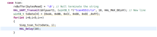
// Write to the TX buffer
TCAN4x5x_MCAN_WriteTXBuffer(0, header, TxData);
// Send the message
TCAN4x5x_MCAN_TransmitBufferContents(0);