This thread has been locked.

If you have a related question, please click the "Ask a related question" button in the top right corner. The newly created question will be automatically linked to this question.

TCAN4550EVM: Not able to transmit CAN message from TCAN4550

Part Number: TCAN4550EVM
Other Parts Discussed in Thread: TCAN4550, TCAN4550-Q1

Hi,

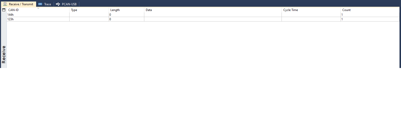
I am working on TCAN4550 with NXP(i.mx 8M Nano board) to be able to transmit and receive the CAN messages .I am using PCAN simulator to see the transmitted and received CAN messages. I am able to receive the message from TCAN board to NXP board  but while transmitting the CAN messages from NXP board to TCAN board am able to send 0 length payload to TCAN4550(CAN message with its message id and Length =0 received on simulator).I have attached screenshot of PCAN simulator .your guidance will be highly appreciated.

  • Bipin,

    Thanks for bringing this to our attention, can I ask for what application this is being developed? 

    Also, in the title of your thread you mention not being able to transmit from the TCAN4550-Q1, but in the body of the post it sounds like you can't receive. I just want to clarify which you are having trouble with.

    Also, if you go to the TCAN4550-Q1 product folder on TI.com, there is a software user's guide that goes step by step on how to receive and send messages with the TCAN4550-Q1 device. I recommend reading through this while debugging your issue.

    Regards,

  • Hi Eric,

    Sorry for the confusion .I am trying to send the CAN messages from my NXP NANO board to TCAN4550 but able to send only CAN message ID and not the Payload .I am able to receive the messages from TCAN4550 to NXP NANO board successfully. Hope this clears the confusion now.

  • Bipin,

    Thanks for the clarification. Is it possible for you to read the interrupt registers 0x0820 and 0x0824? I want to see if any interrupts are being thrown that would be stopping the full CAN message from being received by the TCAN4550-Q1.

    Regards,

  • Hi Eric,

    For register 0x820->GLOBALERR,SPIERR

    for register 0x824->PED: Protocol Error in Data Phase (Data Bit Time is used).

    Only Message id can be seen on simulator. Data length is 0 as mentioned earlier.

    Thanks.

  • Bipin,

    Thanks for this information, it looks like there's some sort of error occurring in your CAN frame from the NXP board during the data portion of the frame. Some CAN controllers are configured to stop transmitting as soon as an error is detected, can you find out if the NXP board is configured this way?

    Is there any way you can capture the CANH and CANL signals on an oscilloscope? Also, since there is a SPI error being asserted, that means that an interrupt in register 0x000C is being asserted. Can you read 0x000C to find out where interrupt that is?

    Regards,

  • Eric,

    I can not see the signals on CANL and CANH when used oscilloscope. Also i read the register 000C.I get  "SPI_error_interrupt and Internal_access_active" errors.

    Regards,

    Bipin

  • Bipin,

    Understood about the CAN bus, if no frames are coming through at all, then it seems to be an issue with the NXP device since TCAN4550-Q1 won't do anything to stop transmission as the receiver. Is there a way to check for any interrupts or errors on the NXP board?

    Regards,

  • Eric,

    I guess no issue with the interrupt on NXP board as we are using only SPI communication on NXP board. Is it possible that we are writing CAN data to TCAN4550 but its not getting written there and hence we are not getting the data?

    Regards,

    Bipin

  • Hi Eric,

    One more doubt. Start address of TX buffer in MRAM  is 0x8270 in datasheet. But when i am  using function "TCAN4x5x_MCAN_WriteTXBuffer()"provided by TI, Start address calculated is 0x81bc.is it like the calculated start address is wrong and that's why we are not able to write data in appropriate tx buffer due to which we are unable to receive the data ??.I am pasting the function definition here for your reference so that you can see how the start address is calculated in function.

    Please correct if my understanding is wrong.

    /////////////////////////////////////////////////////////////////////////////////////////////////////////////////////////////////////////////////////////////////////////

    TCAN4x5x_MCAN_WriteTXBuffer(uint8_t bufIndex, TCAN4x5x_MCAN_TX_Header *header, uint8_t dataPayload[])
    {
    // Step 1: Get the start address of the
    uint32_t SPIData;
    uint16_t startAddress;
    uint8_t i, elementSize, temp;


    // Get the TX Start location and size...
    #ifdef TCAN4x5x_MCAN_CACHE_CONFIGURATION
    SPIData = TCAN4x5x_MCAN_CACHE[TCAN4x5x_MCAN_CACHE_TXBC];
    #else
    SPIData = AHB_READ_32(REG_MCAN_TXBC);
    #endif
    startAddress = (uint16_t)(SPIData & 0x0000FFFF) + 0x8000;
    // Transmit FIFO and queue numbers
    temp = (uint8_t)((SPIData >> 24) & 0x3F);
    elementSize = temp > 32 ? 32 : temp;
    // Dedicated transmit buffers
    temp = (uint8_t)((SPIData >> 16) & 0x3F);
    elementSize += temp > 32 ? 32 : temp;

    if (bufIndex > (elementSize-1)) {
    return 0;
    }

    // Get the actual element size of each TX element
    #ifdef TCAN4x5x_MCAN_CACHE_CONFIGURATION
    SPIData = TCAN4x5x_MCAN_CACHE[TCAN4x5x_MCAN_CACHE_TXESC];
    #else
    SPIData = AHB_READ_32(REG_MCAN_TXESC);
    #endif
    elementSize = TCAN4x5x_MCAN_TXRXESC_DataByteValue(SPIData & 0x07) + 8;

    // Calculate the actual start address for the latest index
    startAddress += ((uint32_t)elementSize * bufIndex);

    // Now we need to actually check how much data we are writing (because we don't need to fill a 64-byte FIFO if we are sending an 8 byte can packet)
    elementSize = (TCAN4x5x_MCAN_DLCtoBytes(header->DLC & 0x0F) + 8) >> 2; // Convert it to words for easier reading by dividing by 4, and only look at data payload
    if (TCAN4x5x_MCAN_DLCtoBytes(header->DLC & 0x0F) % 4) { // If we don't have a whole word worth of data... We need to round up to the nearest word (by default it truncates). Can be done by simply adding another word.
    elementSize += 1;
    }
    // Read the data, start with a burst read
    AHB_WRITE_BURST_START(startAddress, elementSize);
    SPIData = 0;

    SPIData |= ((uint32_t)header->ESI & 0x01) << 31;
    SPIData |= ((uint32_t)header->XTD & 0x01) << 30;
    SPIData |= ((uint32_t)header->RTR & 0x01) << 29;

    if (header->XTD)
    SPIData |= ((uint32_t)header->ID & 0x1FFFFFFF);
    else
    SPIData |= ((uint32_t)header->ID & 0x07FF) << 18;

    AHB_WRITE_BURST_WRITE(SPIData);

    SPIData = 0;
    SPIData |= ((uint32_t)header->DLC & 0x0F) << 16;
    SPIData |= ((uint32_t)header->BRS & 0x01) << 20;
    SPIData |= ((uint32_t)header->FDF & 0x01) << 21;
    SPIData |= ((uint32_t)header->EFC & 0x01) << 23;
    SPIData |= ((uint32_t)header->MM & 0xFF) << 24;
    AHB_WRITE_BURST_WRITE(SPIData);

    // Get the actual data
    elementSize = TCAN4x5x_MCAN_DLCtoBytes(header->DLC & 0x0F); // Returns the number of data bytes
    i = 0; // Used to count the number of bytes we have read.
    while (i < elementSize) {
    SPIData = 0;
    // If elementSize - i < 4, then this means we are on our last word, with a word that is less than 4 bytes long
    if ((elementSize - i) < 4) {
    while (i < elementSize)
    {
    SPIData |= ((uint32_t)dataPayload[i] << ((i % 4) * 8));
    i++;
    }

    AHB_WRITE_BURST_WRITE(SPIData);
    } else {
    SPIData |= ((uint32_t)dataPayload[i++]);
    SPIData |= ((uint32_t)dataPayload[i++]) << 8;
    SPIData |= ((uint32_t)dataPayload[i++]) << 16;
    SPIData |= ((uint32_t)dataPayload[i++]) << 24;

    AHB_WRITE_BURST_WRITE(SPIData);
    }

    if (i > elementSize)
    i = elementSize;
    }
    AHB_WRITE_BURST_END(); // Terminate the burst read

    return (uint32_t)1 << bufIndex; // Return the number of bytes retrieved
    }

  • Bipin,

    Okay I understand now, I thought the NXP board was another CAN controller.

    As for the TX buffer start address, this doesn't need to be 0x8270, it's dependent on your own memory allocation in the application. In the software user's guide, the example used found the TX buffer start address to be 0x8270, but this is not a defined start address.

    Since there is a protocol error in the data phase being reported, the message itself is not completing it's full transmission, so this is why no data is being received. In register 0x1018 bit 6 is the DAR bit. This enables the ability for the controller to continuously resend a message if it was not transmitted correctly. Can you check the status of this bit? I want to make sure it is set to 0 so the controller will continuously send the frame and you can capture the waveform. We need to understand what is causing the protocol error in the data phase to figure this out I believe.

    Regards,