This thread has been locked.

If you have a related question, please click the "Ask a related question" button in the top right corner. The newly created question will be automatically linked to this question.

DS90UB947-Q1: DS90UB948-Q1

Part Number: DS90UB947-Q1
Other Parts Discussed in Thread: DS90UB948-Q1

Tool/software:

Hello TI,

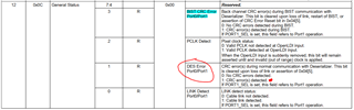
I'm having a project use ds90ub947-q1 and ds90ub948-q1 (FPDLinkIII Serializer and Deserializer). Our system operated quite normally, UI is also displayed on monitor. Just there is a problem that when I read register 0x0C of 947, it's value is 0x07, it's mean that bit1 is set to 1 --> CRC error(s) detected. This is abnormal, right? And what factors could cause this?

Hope receive help soon!

  • Hi,

    When are you checking the CRC register? Is it right after initialization?

    Registers 0x0A and 0x0B give you the LSB and MSB of the number of CRC errors, have you checked?

    A few CRC errors may occur during initialization but should not accumulate under normal runtime conditions.

    CRC errors come from bit errors on the link and can occur if the link is marginally or not meeting channel specifications or with external interference like EMI.

    Thanks,

    Eddy

  • Hi,

    I read this register after initialization and continuously with cycle 10ms, value of it is also 0x07.

    Is clock of LVDS signal is not enough to adapt with required clock of monitor a cause? I'm having doubts about this

  • Hi,

    You can use the Margin Analysis tab in Analog Launch Pad on the DS90UB948-Q1 profile to check your link integrity.

    Below I have linked an explanation of how to use the MAP Tool in Analog Launch Pad:

    FPD-Link Margin Analysis Program (MAP) user's guide (ti.com)

    As for your LVDS question, I recommend evaluating your clocking output against the specifications in the datasheet. Refer to section 6.6 AC Electrical Characteristics based on the OpenLDI input jitter tolerance to see if it meets specifications.

    Thanks,

    Eddy