DS280DF810: EOM monitor issue and the relationship with EOM timer

Part Number: DS280DF810

Tool/software:

Hi team

Our development product use DS280DF810  for Ethernet Switch. DS280DF810 is place between optical transceiver and SWLSI for 25G transmission.

We have questions about EOM monitor of DS280DF810.

When we repeatedly execute optical signal ON/OFF to the optical transceiver, the EOM monitor value may occasionally become 0 (channel register address 27, address 28).

No matter how many times  we read the address, the value remains 0.

At that time, a communication error or link down occur.

Our experiments have shown that the probability that the EOM monitor value becomes 0 depends on the EOM time.

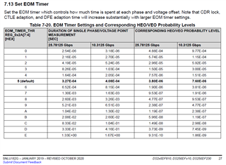
Currently, we use default value of EOM_TIMER_THR REG_0x2A[7:4]=5. In this case we can see that  the EOM monitor value becomes 0.

However, as  decreasing the value, the probability of the value becoming 0 decreases, and as increasing the value, the probability of the value becoming 0 increases.

Also, changing a register (channel register address 67) to 0(disable), the probability of the value becoming 0 increases.


Can you please tell us what you think could be the reason for this result ?

Are there any side effects of using EOM_TIMER_THR REG_0x2A[7:4] with a register value of 0?

Thanks,

K. Mizobuchi

  • Hi Mizobuchi-san,

    I have a couple questions:

    1) In this state where EOM monitor reads 0, does the retimer have CDR lock?  Does it have signal detect?  If it has signal detect, but not CDR lock, what is the value of register 0x02?

    2) Will a CDR reset/release procedure fix the EOM issue?  You can set CDR reset by setting ch_reg_0x0A = 0x0C.  You can release reset by setting ch_reg_0x0A=0x00.

    My current hypothesis is that for some reason during a laser off/on sequence, the retimer reads a low HEO/VEO value when it tries to link.  This could affect CDR lock.

    Are there any side effects of using EOM_TIMER_THR REG_0x2A[7:4] with a register value of 0?

    Using EOM_TIMER_THR_REG_0x2A[7:4] with register value of 0 will mean that HEO/VEO is measured at a higher probability level.  Since the measurement is not being taken for as long, it may not catch lower probability jitter in the HEO/VEO measurement.  This could impact the CTLE/DFE values that the retimer adapts to since it uses the HEO/VEO values for adaptation.

    Thanks,

    Drew

  • Hi Drew-san

    Thank you for your reply.

    1) In this state where EOM monitor reads 0, does the retimer have CDR lock?  Does it have signal detect?  If it has signal detect, but not CDR lock, what is the value of register 0x02?

    => We will check them.

    2) Will a CDR reset/release procedure fix the EOM issue?  You can set CDR reset by setting ch_reg_0x0A = 0x0C.  You can release reset by setting ch_reg_0x0A=0x00.

    =>Yes, CDR reset/release procedure can fix the EOM issue. But when we use CDR reset/release to fix it, link down occurs. So, CDR reset/release is not a solution.

    Thanks,

    K. Mizobuchi

  • Hi Mizobuchi-san,

    Drew is out of office until 7/18, so I will be covering for him in the meantime.

    Thank you for trying Drew's suggestions. It will be good to understand CDR lock and signal detect behavior when the EOM monitor reads 0.

    I have another debug suggestion. Can you measure eye opening and jitter performance of the retimer output when EOM_TIMER_THR_REG_0x2A[7:4]=0? Can you compare this measurement to eye opening and jitter performance when EOM_TIMER_THR_REG_0x2A[7:4]=5? I'd like to see if there is any noticeable performance difference when you reduce the EOM timer threshold.

    Best,

    Lucas

  • Hi Lucas-san

    1) In this state where EOM monitor reads 0, does the retimer have CDR lock?  Does it have signal detect?  If it has signal detect, but not CDR lock, what is the value of register 0x02?

    =>In this state where EOM monitor reads 0x00, register 0x02=0xD8, register 0x78[4]=1, register 0x78[5]=1  So, seem no problems.

        After CDR reset, EOM monitor reads 0x20, register 0x02=0xD8, register 0x78[4]=1, register 0x78[5]=1  So, seem no problems.

    About another debug suggestion, We can not measure eye opening and jitter performance of the jitter performance.

    But in case of EOM_TIMER_THR_REG_0x2A[7:4]=0, we always see the EOM monitor read 0x20, however, frame errors are happened once in a while when we repeatedly execute optical signal ON/OFF to the optical transceiver. So, CDR lock time and CTLE time may not be optimal.

    Best Regards,

    K.Mizobuchi

  • Hi Mizobuchi-san,

    Thank you for checking CDR lock behavior. I understand you are not able to measure eye opening and jitter performance.

    When you say EOM monitor reads 0x20, are you referring to reg_0x27?

    Additionally, can you bring up the retimer with EOM_TIMER_THR_REG_0x2A[7:4] = 0 versus 5 a few times? After each bringup, can you read registers 0x8f, 0x11, 0x12, 0x20, and 0x21? I'd like to check CTLE and DFE adapted values to see if there is a clear adaptation difference depending on EOM timer threshold value.

    Best,
    Lucas

  • Hi Lucas-san

    When you say EOM monitor reads 0x20, are you referring to reg_0x27?

    =>No. EOM monitor read value means reg_0x29.

    can you read registers 0x8f, 0x11, 0x12, 0x20, and 0x21?

    Reg_0x67[5]=0

    We use REG_0x31[6:5]=1(Default) as ADAPT MODE. The CTLE automatically adapts.  The DFE is disabled. 

    Thanks,

    K.Mizobuchi

  • Hi Lucas-san

    We have additional questions below,

    1. Can the value of Reg_0x8F be seen only when Reg_0x31[6:5]=1 (adaptive CTLE)?  Is the value in that case as shown in Table 7-29. CTLE Boost Table of the data sheet ?

    2. In case of Reg_0x31[6:5]=0(manual CTLE), should we check by writing and reading using Reg_0x03?

    3. When changing the CTLE value, does the EOM monitor value(Reg_0x27, 0x28, 0x29) change ? Please tell us the relationship between CTLE value and EOM monitor value ?

    Thanks,

    K.Mizobuchi

  • Hi Mizobuchi-san,

    Our team will get back to you tomorrow.

    Best,

    Evan Su

  • Hi Mizobuchi-san,

    Thanks for sharing this data.

    1. The value of reg_0x8F is valid for all adapt modes.  These values correspond to the values as shown in table 7-29.

    2. In adapt mode 0 reg_0x31[6:5]=0, you can set the CTLE value in register 0x03.  You can read back from this register as well.

    3. The internal eye measured by the eye opening monitor is measured after the CTLE and DFE have been applied to the signal.  This means that the better a signal is equalized, the larger the eye opening.  If the CTLE value is poor, then the HEO/VEO will be reduced.

    How does channel insertion loss prior to the retimer correlate to the ports in your data?  Does it make sense that port 9 and 11 tend to have more CTLE applied?

    As an experiment, if you manually set CTLE to a value that has good HEO/VEO and good BER performance, does this resolve the issue?

    Thanks,

    Drew

  • Hi Drew-san

    How does channel insertion loss prior to the retimer correlate to the ports in your data?  Does it make sense that port 9 and 11 tend to have more CTLE applied?

    If we consider ports insertion loss prior to the re-timer, value of 0x8F=00(9.2dB) is appropriate for all ports. Value of 0x8F=40-D5 is too strong.

    We think that CTLE adaptive control is not appropriate. So, we will use CTLE manual not adaptive.

    Thanks,

    K. Mizobuchi