- Ask a related questionWhat is a related question?A related question is a question created from another question. When the related question is created, it will be automatically linked to the original question.
This thread has been locked.
If you have a related question, please click the "Ask a related question" button in the top right corner. The newly created question will be automatically linked to this question.
Tool/software:
Dear Sir /Madam,
Right now we have changed Device but complexity i am getting that new Device ( MASW-008322 ) required new logic ,which are 2 line instead of 1 logic line .
can you please check following requirement .
| original logic | Required logic |
| 0V | (-5V) |
| (0V) | |
| (+5V) | (0V) |
| (-5V) |
can it be possible using 26LS31 .
A differential line driver like the AM26xx31 outputs RS-422 voltages, which are not what you want.
It might be possible to use comparators. What power supplies do you have available? What is the required switching speed?
Dear Clemens sir,
I need basic logic circuit which perform simple work ,can you please suggest we will preferred SMD component as we have size constrains.
1. Power supplies available are +15V and +5V .
2 . we need 1uSec max. switching speed .
Without a negative supply, you will not be able to generate a −5 V output signal.
Hi sir , can you recommend some ic ,which generate -5v .
Means input logic act as enable pin to negative voltage generator IC?
Hi Tapajit,
The only devices we would have that would be able to generate a negative voltage relative to GND without a negative supply would probably be our RS232 devices which are single ended (one line) but the outputs would swing from +5V to -5V.
You would probably need to generate some kind of negative power supply to get what you're looking for.
-Bobby
Hi BOBBY sir ,
can MAX889 (negative generator ) and NLVHC1G14DFT1G( inverter) it is possible .
what is exact topology ?
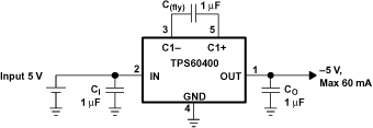
TI offers many negative power supplies; see this search: ti.com/power-management/acdc-dcdc-converters/products.html#1241=Charge pump&634min=-32;-5. The MAX889's equivalent would be the TPS60400.

To generate the output signals, use comparators to compare the input signal against a refernce of 2.5 V. You would need comparators with split supplies, e.g., TLV1872, with the input supplies ±5 V, and the output supplies −5 V and 0 V.
Dear Sir,
i understood following is it work? ,

or can we go ahead with NOT gate and Inverter as follow ,

if yes which NOT ic work on single +5V .
The 74xx14 is called an inverter because it inverts the logic level, i.e., it converts 0 V to 5 V, and 5 V to 0 V. It does not support or generate negative voltages.
You must combine a negative power supply and comparators.
Use something like the TPS60400 to generate the −5 V power rail. Then use comparators (as in your first circuit).
Dear sir,
what I want is E2 is singe input and i need 2 output V1 and V2 ,is it circuit right .
Driving the switching regulator's IN pin looks like it would turn the device off. With the 100k resistors, an RC circuit is created and the V1/V2 nodes would probably take some time before they get to the GND voltage.
-Bobby