Other Parts Discussed in Thread: C2000WARE,
Tool/software:
Hi everyone,
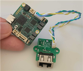
We have a design based on the Launchpad F28P65. We pretty much copied the schematic of the board, but we cannot get the EtherCAT communication working. The only difference is the use of discrete magnetics, but this worked with previous EtherCAT designs (using DP83822IRHBR PHY and LAN9254 Microchip), so I don’t think this is the problem.
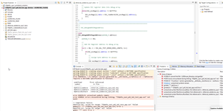
Trying to use f28p65x_cpu1_pdi_hal_test_app from C2000Ware_5_02_00_00, when we try to build in flash, I get the error: “Target is TMS320F28P650DK9.ccxml and the above error is reported. "Cannot find a driver for Cpu CPU1_CLA1.” I added the config file from here:
Build OK. I added #define _LAUNCHXL_F28P65X in device.h to set up the GPIOs the same as the launchpad.
Flash the CPU, and in debug mode, it goes into ESC_EEPROM_LOAD_ERROR and the red LED ERROR turns ON.

We are able to read the ESC registers:

We are aware of the issues with the DP83826ERHBR, so I also tried the software patch from here
https://e2e.ti.com/support/microcontrollers/c2000-microcontrollers-group/c2000/f/c2000-microcontrollers-forum/1325322/faq-launchxl-f28p65x-how-do-i-fix-the-ethercat-issue-where-the-launchpad-cannot-be-scanned-in-twincat
With the software patch:
Built in flash, then in debug mode, I can see the RX_MsgBuffer loading only the minimum needed bytes into the EEPROM.

Then I flash the code ethercat_slave_cpu1_hal_PHY_check.c and in debug mode it also get stuck at ESC_EEPROM_LOAD_ERROR and red led ERROR turns ON
return(ESC_EEPROM_LOAD_ERROR);
At power-up, with no RJ45 cable connected, both LEDs (P0 Link Status and Link Active) are ON. When we connect the RJ45, the LEDs (P0 Link Status and Link Active) turn OFF, indicating that something is detected, but I don’t see any slave.
The marking on our PHYs is "826E TI 198 ALSF G4," and we saw the post where there are issues with parts having the exact same marking:
https://e2e.ti.com/support/interface-group/interface/f/interface-forum/1303041/dp83826e-possibly-broken-parts-from-supplier
If we probe:
- Pin 21 PWRDN is at 3V3
- Pin 32 RST_N is at 3V3
- Pin 31 CLKOUT/LED is at 0V
- Pin 19 RX_CLK shows a nice 50MHz
- Pin 9 XIN shows 25MHz
- Pin 10 RBIAS is at 0V
One last thing to mention: the board originally had a 40MHz crystal instead of 25MHz. We later removed the 40MHz crystal and replaced it with a 25MHz crystal. I don't think that could have damaged the PHY, but I wanted to mention it.
We are a bit out of ideas. Any help would be appreciated.
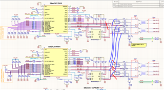
Attached are our schematics.1565.SCH.PDF