


FAQ: Logic and Voltage Translation > IxC >> What is the Auto Increment Feature in I2C IO Expanders?
The auto-increment feature of I2C IO Expanders is when the registers of the device automatically increment to the next register in the set after consecutive writes / reads.
This feature is helpful if the IO expander is being written to or read from constantly. The constant writes and reads take up a lot of bandwidth in the I2C system. Auto incrementation helps to make the software more efficient which is especially helpful with heavily loaded I2C bus systems.
To understand this concept clearly, a picture of how to write a single byte to an I2C IO expander is shown below:
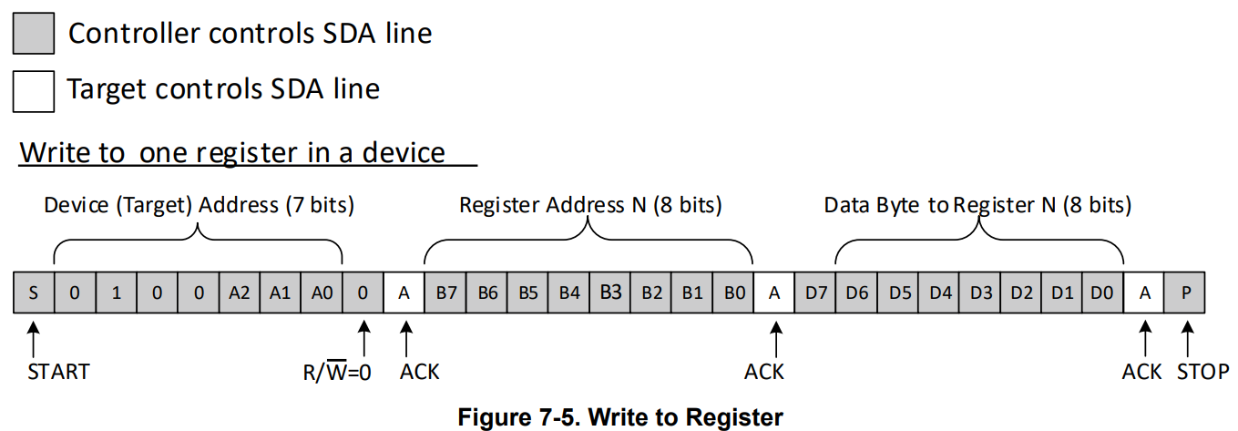
In the first byte, the device (target) 7 bit address is sent. Next is the "pointer" byte or register address. This is the register being written to. Finally, the third byte is the data to be set in the register selected.
In total, it takes 3 bytes of data to complete a single write transaction. For an 8-bit (8 IO) expander, this byte format is convenient since a single write can be utilized to change the state of 8 IO's at one time.
In the case that an IO expander has many GPIO's such as the 24-bit I2C IO expander TCA6424A. This same byte format would require 9 bytes of data in order to change all 24 IO's since it must write 8 bits at a time.
3 devices addresses, 3 register addresses, 3 data bytes for each register address
Auto incrementation removes the need to establish the pointer address every time a transaction is made. For example, if the user wants to write from all input port registers of the TCA6424A (Input port 0, Input port 1, Input port 2), the user can avoid rewriting the device address and the register address and simply continue the write transaction with the next data byte.
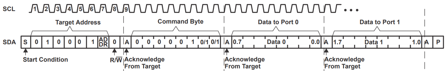
In this figure, the device address followed by the output port register address is sent. Data 0 is written to Output Port Register 0, Data 1 is written to Output Port Register 1, and so on.
Instead of writing 9 bytes of data to configure the 24 IO's, 5 bytes of data can be written.
1 x device address, 1 x output port register 0 address, 3 x data bytes = 5 bytes total.
For more information on the auto increment feature, please see the application note: