Other Parts Discussed in Thread: SN65LBC174A-EP, SN65C1167E
Tool/software:
Hi,
This question is a continuation of the one in the link below.
e2e.ti.com/.../sn65c1167e-alternative-to-sn65c1167e-for-higher-ambient-temperature
Based on the suggested list of Transceivers, I have chosen SN65LBC173A-EP as a receiver and SN65LBC174A-EP as a transmitter. The application is to send the PWM signals (100kHz) from the control board to the gate driver board differentially, whose duty will vary from 5% to 95% (pulse width of 500ns to 9.5us), and the dead time would be between 100ns to 300ns between the PWM’s driving Top and Bottom switch. The distance to be sent would be around 150cm to 200cm.
I plan to use the receiving end circuit, as shown below (Figure 1). The 549-ohm resistors are a failsafe resistor. And 10 ohms series resistors are used from a design guide, “Protecting RS-485 Interfaces Against Lethal Electrical Transients”. I intend to use the TVS diode Between (R7 & R8) and C2.
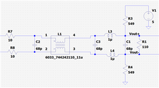
Figure 1: Receiver end circuit
This circuit is similar to the one used in the UCC217XXQDWEVM-054 but has an additional common mode choke with capacitors (Figure 1). The transmitter side circuit is not present in the UCC217XXQDWEVM-054. The signal to be sent goes to the transceiver input channel, and the output differential signal is directly routed to a connector.
1) Is there any suggestion for a transmitter side circuit for the SN65LBC174A-EP?
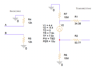
2) As there is no LTspice model for SN65LBC174A-EP, I tried an LTspice simulation with SN65C1167E (as given in the UCC217XXQDWEVM-054). I am aware of the fact that SN65C1167E is an RS422. However, since the models for SN65LBC173A-EP and SN65LBC174A-EP are not available, I went with this option. The model was tried with NO transmitter end circuit (as shown in Figure 2) while using the cable impedance of 120 ohms and Td=50ns.

Figure 2: Simulated Circuit
The simulated circuit gave the below outputs.
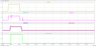
Figure 3: Simulated Circuit (Figure 2) output waveform
Even though the output signal looks fine, there is significant distortion in the transmitted signal. Do you suggest any transmitter side circuit to mitigate these distortions? Any general comments?
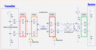
3) I have modified the circuit on the transmitter side as shown below (Figure 4) (i.e., adding an LC filter on the transmitter side).

Figure 4: Modified Simulated Circuit
The output waveforms of the modified circuit are shown in Figure 5. The distortion seems to be a bit better on the transmission side; however, the overall distortion in the transmission and receiving signals is unsatisfactory. Please let me know how to improve the transmission and receiver side circuit to get proper transmission and receiving end signals.
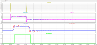
Figure 5: Modified Simulated Circuit (Figure 4) waveform
Additional Information: I have used 549 ohms for fail-safe biasing. So the overall Receiving side impedance will be 110||(2*549) = 99.98 ohms. If we consider series 10 ohms resistors as a part of the load, I thought the overall impedance at the receiving end would be 120 ohms, and hence, I used the cable impedance to be 120 ohms. Is this assumption right?
4) Could you please recommend a TVS diode that could be used for SN65LBC173A-EP and SN65LBC173A-EP. According to the datasheet, diodes need to be bi-directional, and they cannot clamp below -10V or above 15V - and you shouldn't conduct at 6V or less - so the voltage rating needs to be 6V or higher but the max clamped value needs to be in-between -10V to 15V. I am unable to find such TVS diodes that can clamp at -10V and +15V.
Thank you


