This thread has been locked.
If you have a related question, please click the "Ask a related question" button in the top right corner. The newly created question will be automatically linked to this question.
Tool/software:
Hi Team,
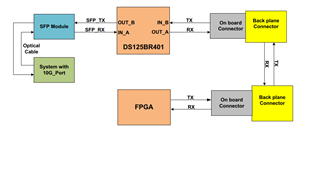
We are using DS125BR401SQE/NOPB in our design for 10G Ethernet links (Do not require link training ) from FPGA to SFP+ interface through back plane connections. We set the redriver in limiting mode by connecting mode pin with pull down resistor to GND.
During 10G Link validation test we observed that out link is getting up, But it creating errors randomly. We tried to optimize the link setting (VOD,EQ,DEM) of DS125BR401S, but still we can not achieve the error free channels.
We configured SD_TH in high state and we set the below mentioned signal detect registers for forcing forcing the Signal Detect function to be always ON.
0x0D[1]= 1'b, 0x14[1] = 1'b, 0x1B[1] = 1'b, 0x22[1] = 1'b
0x2A[1]= 1'b, 0x31[1] = 1'b, 0x38[1] = 1'b, 0x3F[1] = 1'b
Observation 1:
We can able to achieve the error free channel while we set redriver during INB to OUTA loop back mode by writing 21 value in 0x02 register.
We attached the current redriver register value for your reference. Refer attached image for loop back scheme diagram.
After validating back plane level loop back testing, we set 31 value in 0x02 register for normal operation in that case our link itself not active. So we programmed 50 value in 0x08 register & 20 value in register (0E,15,1C,23,2B,32,39 & 40) for idle control from registers to set output ON function.
In this case 10G link up but still we have random error.
Question 1: Can you please suggest what is the suggested setting for 10GbE interface in optical link(With out Auto Negotiation)?
Question 2: In 9.5.1.1.1 section of DS125BR401 data sheet mentioned that “This data loss can be eliminated by disabling automatic detection and forcing the Signal Detect function to be always ON”
How to disable the automatic detection in DS125BR401?
What are register I need to overwrite for this operation?
Thanks in advance,
Esakki.
Sl.No Register Values 1 0x02 21 2 0x06 18 3 0x2D A9 4 0x34 A8 5 0x3B AB 6 0x42 A9 7 0x10 A8 8 0x17 A8 9 0x1E A8 10 0x25 A8 11 0x2E 0 12 0x35 0 13 0x3C 0 14 0x43 0 15 0x11 0 16 0x18 0 17 0x1F 0 18 0x26 0 19 0x2C 0 20 0x33 0 21 0x3A 0 22 0x41 0 23 0x0F 0 24 0x16 0 25 0x1D 0 26 0x24 0 27 0x08 50 28 0x01 0 29 0x0D 2 30 0x14 2 31 0x1B 2 32 0x22 2 33 0x2A 2 34 0x31 2 35 0x38 2 36 0x3F 2 37 0x0E 20 38 0x15 20 39 0x1C 20 40 0x23 20 41 0x2B 20 42 0x32 20 43 0x39 20 44 0x40 20 45 0x12 0F 46 0x19 0F 47 0x20 0F 48 0x27 0F 49 0x2F 0F 50 0x36 0F 51 0x3D 0F 52 0x44 0F
Hi Esakki,
Which RX-detect setting are you currently using? For 10 GbE applications, manual RX-detect with input termination of 50 ohm should be used. This can be configured by pulling the RXDET pin high or programming 0x08[3]=1, 0x0E[3:2]=11, 0x15[3:2]=11, 0x1C[3:2]=11, 0x23[3:2]=11, 0x2B[3:2]=11, 0x32[3:2]=11, 0x39[3:2]=11, 0x40[3:2]=11.
"Disabling automatic detection" refers to using manual RX-detect setting.
Have you tried using loopback IN_A to OUT_B? I'm curious if this configuration resulted in no errors as well.
Best,
Lucas
Hi Lucas,
We are using manual RX-detect with input termination of 50 ohm option only. We already pulled RXDET pin high through pull up resistor to VDD. So currently we set redriver in manual Rx- Detect settings only.
We tried loop back in IN_A to OUT_B path, We can able to achieve the error free channel.
We are facing issues while we set 0x31 data in 0x02 Address for normal operation.
Question 1: Can you please suggest is there any other settings for 10GbE interface we need to program?
Thanks in advance,
Esakki.
Hi Esakki,
Thank you for your feedback. I'd like to check, what testing was performed to optimize EQ, DEM, and VOD values? Optimizing these values is critical to error free operation. My recommendation is to optimize these values based on eye opening.
Additionally, is this E2E thread related? If this is the same project, can you clarify if DS125BR401 or DS100KR401 is being used?
Best,
Lucas