This thread has been locked.

If you have a related question, please click the "Ask a related question" button in the top right corner. The newly created question will be automatically linked to this question.

DS125DF111: Retimer initial programming sequence

Part Number: DS125DF111

Tool/software:

We are using the DS125DF111 XFI retimer in our current project. We are having some difficulty programming the retimer.  

Could you please help review the sequence below and let us know if we are missing anything?

This is what we are writing to the register space:

Register

Value

R/W

Reason

0xFF

0x0C

W

Broadcast to all channel

0x0A[3:2]

0x1C

W

CDR reset override

W

Enable CDR reset override

0x60

0x00

W

VCO frequency settings

0x61

0xB2

W

0x62

0x90

W

0x63

0xB3

W

0x64

0xCD

W

0x0A[3:2]

0x1

W

Release CDR reset

Do we need to write back to 0xFF register space anything at the end to get the retimer to lock to the input?

  • Hi Abeed,

    Your register write sequence generally looks good and I don't see any major issues. I do have a few comments.

    • Your VCO configuration selects data rates 10 Gbps and 10.3125 Gbps. Were these your intended selections?
    • We typically recommend using 0x64=0xFF to increase the PPM threshold for CDR lock. I don't expect this to make a big difference compared to 0x64=0xCD.
    • There may be a typo on your last line. Can you confirm you are writing 0x0A=0x10 to release CDR reset?

    You do not need to write back to register 0xFF at the end of your sequence.

    • Are you having trouble obtaining CDR lock?
    • Can you share the data rate and pattern being transmitted to the retimer?

    Best,

    Lucas

  • Hi Lucas,

    I have used this part in my previous design and the schematic and layout implementation is the same. I lost my previous correspondences from a few years ago regarding the programming sequence of these retimers. 

    We are looking at our SoC and ethernet switch side of things right now to make sure we are ok on that front. But as of now ethernet link is not yet up. Hence, this post is to reconfirm whether the sequence is correct and nothing out of the ordinary.

    Responses to your questions in-line below...

    • Your VCO configuration selects data rates 10 Gbps and 10.3125 Gbps. Were these your intended selections?
      • [Abeed] Yes, it is a 10Gbps MGBE interface
    • We typically recommend using 0x64=0xFF to increase the PPM threshold for CDR lock. I don't expect this to make a big difference compared to 0x64=0xCD.
      • [Abeed] We can try this.
    • There may be a typo on your last line. Can you confirm you are writing 0x0A=0x10 to release CDR reset?
      • [Abeed] yes that's a typo. 
    • Are you having trouble obtaining CDR lock?
      • [Abeed] I am unsure, are their registers to check whether there are signal patterns at the input and CDR lock was attempted? We are trying to set up scopes to see if there are incoming patterns from our SoC.
    • Can you share the data rate and pattern being transmitted to the retimer?
      • [Abeed] data rate is 10Gbps, I'll get back to you about the pattern that is being transmitted.

    Question: Do we need to write sequentially to bits 2 and 3 at register 0x0A to enable override and do CDR reset? Or is it OK to write at once 0x1C to 0x0A?

    Thanks,

    Abeed 

  • Hi Abeed,

    I understand, thank you for sharing a bit more background on your project. Given your answers, I don't see any issue with your register write sequence.

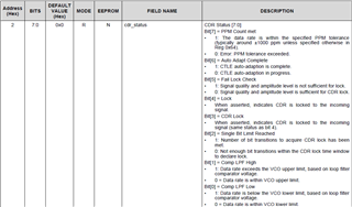
    To answer your questions, yes there are status registers which indicate signal detect and CDR lock.

    • Signal detect observation bit: 0x54 bit 7
    • CDR status: 0x02
      • Bits 3 and 4 indicate CDR lock
      • Other bits share a bit more information about why CDR may not be locking. Please refer to the full register description.

    Please let me know what values you see in these registers.

    Question: Do we need to write sequentially to bits 2 and 3 at register 0x0A to enable override and do CDR reset? Or is it OK to write at once 0x1C to 0x0A?

    It is ok to assert both bits at the same time by simply writing 0x0A=0x1C.

    Best,

    Lucas