This thread has been locked.

If you have a related question, please click the "Ask a related question" button in the top right corner. The newly created question will be automatically linked to this question.

THVD8000: THVD8000

Part Number: THVD8000
Other Parts Discussed in Thread: THS6222, THVD8010

Tool/software:

Hi,

in my Building Automation / HVAC application Imight have up to 30 nodes, the protocol is Modbus 9600b/s, the power cable maximum lenght could be 300 meters.

I would like to know if the THVD8000 can be used in such an application where, instead of using the 4 wires Modbus RTU cable to interface the several sensors and thermostats with the Control Unit, you can use the power line (230V). Or the 24VDC?

Thanks.

Michele Ammendola

  • Hi Michele,

    Yes - the THVD8000 should be able to support that application. The THVD8000 can easily hit 300 meters with the 9.6kbps data rate - all modulation frequencies will be able to support data rate. 

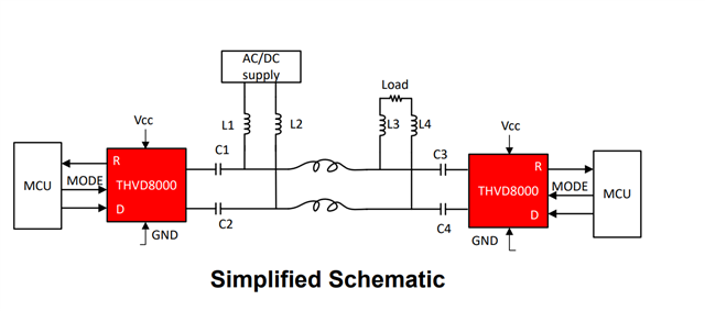
    I will note that in general the THVD8000 is used to communicate on a shared bus  - so between nodes it can be two wire - but at the coupling network there are 4 wires still. 

    So the communication isn't directly on the power line - but the power and data are combined into one bus. The reason I am being pretty specific on that is because there are applications were you inject data onto the actual power bus (no inductors as shown as above) - but that type of application is generally much more complex and if you can avoid it I would. 

    That being said:

    The simplest solution is connecting to the 24V DC bus - so the DC supply in the above figure would be 24V. You should be able to support 30 nodes in this application without much issue. The datasheet basically gives all the guidance you need to finish the 24V DC bus - I have also added the design guide and an excel calculator to size the capacitors and inductors of the coupling network. 

    THVD8000 Design Guide

    3404.THVD80x0_Design_Calculator.xlsx

    Since you have 30 nodes I'd prioritize the values given in the excel sheet above instead of the datasheet calculations. The datasheet equations neglect loading from other transceivers on the bus - the excel calculator does not. For smaller node counts (<10) the equations in both the excel sheet and datasheet are really close - but for higher node counts you should use the excel file attached. 

    Now with that being said - you technically can use the THVD8000 in applications where the data would be directly injected onto a high voltage rail AC or DC - so the 230V can be done. I have added a link to the high voltage reference design below. However, it is important to note that that application requires an additional line driver (THS6222 is what we used for testing), a pulse transformer at every node (the communication node and power line are separated by a transformer) - the THS6222 also operates at a different voltage rail than the THVD8000 so the system would need to be able to power both devices. Also there is generally a lot more filtering and protection recommended than standard implementations.  It is more complex and I'd suggest you look at the standard implemenation over the high voltage one - but it is an option still. 

    THVD8000 HV Design:

    Please let me know if you have any other questions!

    Best,

    Parker Dodson

  • Thank you very much Parker for your detailed answer!

    Let me analyze the option you suggest first, the 24VDC (let's keep the 230VAC for later).

    Imagine I have a Main Central Unit with a RaspberryPi Pico2 controller with a a standard RS485 Modbus interface on one side where the 24VDC is available too.

    Then I have 30 Thermostats with RaspberryPi Pico with the same standard RS485 Modbus intarface on the other side.

    Between the Main Central Unit and the 30 thermostats there is a 4 wire Modbus expensive and complex network.

    I understand that I can use a 2-wire connection between the 31 nodes. Is that correct?

    If yes, what type of wires could those be? Standard and cheap 24VDC power wires? Or shielded and twisted like the expensive Modbus cable?

    Can I use any topology among the 31 nodes?

    One stupid question is: whouc could the "load" be in your picture?

    Thanks.

    Michele

  • Modbus and other differential protocols can also run over cheap cables, but then they are much more sensitive to noise.

    The load is any device that consumes power. In your application, that would probably be the power supplies of all nodes.

  • Thanks Clemens,

    could you answer the topology question?

    In other words, can I use a "tree" type of topology to connect 30 or more nodes for example?

    Thanks,

    Michele Ammendola

  • Hi Michele,

    For your first scenario - yes you can use a two wire connection between all 31 nodes  as the shared bus allows for power and data on the same bus which can reduce total wiring. Modbus and other RS-485 based standards can use the THVD8000 to replace the 4-wire (A, B, PWR, and GND) to only need two wires. 

    As far as cabling selection goes - ideally it is always best to use 120 ohm twisted pair cable for data - however with that being said the vast majority of THVD8000 applications use non-impedance controlled wire - i.e. pretty standard power cabling for the shared bus that is not ideal in standard RS-485 based standards. Essentially - most applications use whatever is easiest for them to use and it generally isn't too problematic. 

    If you look at our THVD8000 Design guide we do have a chart of max distances with a specific wire (20 AWG UL2464 power cables - which is not impedance controlled cable)

    As stated in above table a 'y' indicates that data reception occurs with up to 20% jitter - if it goes above 20% jitter it will be marked with "n". In general the jitter will be lower if you are not maxing out distance vs. modulation frequency. 

    But we have also tested with standard RS-485 120 ohm twisted cable and you should expect similar results to standard RS-485 (a little better because the THVD8000 receiver is more sensitive than standard RS-485 - if you don't want that sensitivity look at the THVD8010 which is more noise immune and with your data rate you don't necessarily need the THVD8000) 

    Beyond that - we have also tested 100 feet/30.5m thermostat cable  (generic thermostat 18/2 cable) at 1Mbps with 5MHz (which is actually pushing the device past its recommended max data rate) and saw it worked okay - while your system is longer we have tested a few sets of cabling and they all seem to work okay. 

    Basically the tradeoff is that if you use the non-impedance controlled power cable the 120 ohm terminations resistors at either end of the bus aren't as effective as if you have 120 ohm twisted pair cable because reflection coefficient = (ZL - Z0)/(ZL+Z0) - where ZL is our termination resistor and Z0 is the characteristic impedance of the cable - when Z0 = ZL the reflection coefficient is 0 which improves signal integrity on the bus. With non-impedance controlled wire Z0 = ? - and it may vary across length of wire causing multiple transmission boundary in which reflections could occur. The 120 ohm will still do something and it will be better than nothing - but it won't be perfect as what we'd generally shoot for in RS-485 based PHY's. 

    Most designers still will use non-impedance controlled cable and it usually doesn't cause too much issue. For your specific application I see three reasons why using non-impedance controlled cable shouldn't be that big of an issue. 

    1. You have a low data rate - at 9.6kbps you can use the lowest modulation frequency of 125KHz. The energy that is prone to reflect is energy in the frequency bands where transmission effects apply. For any RS-485 device (or any pulse train really)  this can be broken into three main components which are the fundamental frequency, harmonics (we consider the pulse train an odd signal so only odd harmonics exist in analysis), and the energy due to signal transitions (rise/fall time of differential signal - as the pulse train is a trapezoidal pulse train). So if we just look at the 125KHz signal the fundamental frequency is 125KHz and if we convert that to its wavelength it is Vp/f_0 -- where Vp is the phase velocity (generally I use 78% * c as that is the most common value I usually see - this will come from the cable - if it is spec'd directly). So the wavelength of 125KHz on a bus with Vp = 78% * c - so the wavelength is 1870m - and if the bus is 1/10th of the wavelength you should consider reflections. So you wouldn't start to see reflections until about 187m from the fundamental frequency. So if the bus is 300m you could see some reflections without termination - but adding termination will also mitigate that farther. You can do a similar analysis for the harmonics (it just results in reflections could start occurring for the nth harmonic at 187/n). The transition time will be based on the driver itself - where reflections can start occurring due to transition time at  t_transition/10 * Vp --> this will be the shorter one. However with this part - you generally only need to concern yourself with the fundamental frequency - which leads into point 2. 

    2. The THVD8000 has an integrated bandpass filter on the demodulator - while we don't directly spec the pass band - it is pretty large (large enough where FDMA isn't really possible) - but in general the 3rd harmonic and higher frequency energy is filtered out by the demodulator on the receiver - so the higher frequency reflections shouldn't impact data integrity too much - the only real concern is reflections from the fundamental frequency - which can be mitigated with proper terminations - it isn't perfect but it generally works. 

    3. The bus length being up to 300m is relatively short (in terms of max distance this device can do) - and since the data rate is lower you can keep modulation frequency lower - which means you generally can avoid a lot of AC loss and only need to really worry about DC loss - which at 300m usually isn't going to be much. The reason this is important is because the THVD8000 has a strong drive strength so even if you do see reflections - lets for example say we have 500mV of reflection and it destructively interferes with an incident signal of magnitude 3.5V - the resulting wave could be 3V now due to the reflection  - however since the THVD8000 treats 3.5V and 3V the same - the data stream wouldn't necessarily be impacted. 

    Now this gets a bit more complicated with worse results as you increase modulation frequency - there is no application reason that would require you to increase from minimum modulation frequency - but there is a more system related reason why you may want higher modulation frequencies and that is because higher modulation frequencies means smaller decoupling inductors - and in the current system with 31 nodes and assuming minimum modulation frequency each inductor would need to have an effective inductance during operation of 16.8mH - where at highest modulation frequency you are only looking at 421uH per inductor (there would 62 inductors in system). From a best performance standpoint I do think the lowest modulation frequency would be best - but from a practical standpoint those inductors are large - if the system you are working with can handle it I'd still suggest it however. 

    As for the "load" - it really can be anything but in general it usually is a SMPS or LDO with bulk input capacitance for DC systems and rectifiers for AC systems - but it doesn't necessarily have to be. In general the standard implementation the THVD8000 wants to see "AC GND" past the inductors - so as far as the THVD8000 is concerned the power load and power source might as well be AC ground - and usually with the assumed bulk capacitance included for the power supplies it basically is "GND" to the THVD8000 while it isn't "GND" for the power signal. 

    I know this is a lot of information - so please don't hesitate to follow up with me if you have any other questions! 

    Best,

    Parker Dodson