This thread has been locked.

If you have a related question, please click the "Ask a related question" button in the top right corner. The newly created question will be automatically linked to this question.

TMDS1204: HDMI 2.1 FRL mode

Part Number: TMDS1204

Hi Team,

We are testing HDMI 2.1 in FRL mode with FRL monitor and Ultra High speed cable.
The TX log shows Video out is lock and Stream is up, but still no output is observed in the monitor.
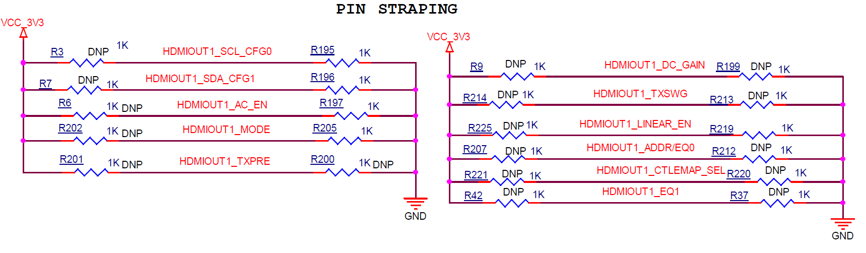
I am running 4 lanes at 8 Gbps FRL mode, is there any Pin strap setting or optimization or register configuration to be done with the remiter?
I have attached the retimer settings for reference

Regards,
Irfan

image.png

  • Hi,

    If this is a sink side design, then I would have LINEAR_EN pin to be floating to enable TMDS1204 into the linear mode. 

    You can then turn the EQ0/EQ1 to see if there is an output on the monitor. 

    Thanks

    David

  • Hi David,

    Please note that in this, Mode pin is Pulled up.
    Also please suggest the EQ0 and EQ1 setting to achieve the high EQ gain.

    Regards,
    Irfan

  • Irfan

    With Mode pin pulled up, TMDS1204 is in pin-strap mode with flexible receiver equalizer with no fan-out buffer support. Is this a source or a sink side design? If it is a source side design, then I would recommend to use fixed equalizer and EQ0/1 need to be tuned depends on the pre-channel insertion loss. 

    Can you please share the schematic for review?

    Thanks

    David

  • Hi David,

    Kindly find the attached schematics for your reference.
    Also, can you share any reference where HDMI 2.1 pin strap setting is implemented based on the requirement of HDMI 2.1.
    We are currently debugging TX(Source) to the monitor.
    How does a pre channel insertion loss be calculated.

    DESIGN2.pdf

    Regards,
    Irfan

  • Irfan

    Looking at the schematic, how are you implementing the DDC bus? The TMDS1204 has integrated pullups to VIO on the DDC LV pins. Therefore, no external pull-ups shall be present between the TMDS1204's DDC LV pins.

    Thanks

    David

  • David,

    I have tested it removing the DDC PU which i have given externally.
    how does this effect HDMI 2.1 operation? 
    How does a pre channel insertion loss be calculated.

    Regards,
    irfan

  • Irfan

    The PU on DDC will impact both TMDS and FRL. There is internal pulldown on the LV_DDC and the LV side pulldown is not enabled unless the LV voltage goes below VILC. If having external pullup, then you are preventing the LV side pulldown ever gets enabled. 

    For pre-channel insertion loss rough calculation, please see this link: https://www.edn.com/loss-in-a-channel-rule-of-thumb-9/

    Thanks
    David 

  • David,

    There is no effect of removing the PU's on DDC lines, the output is still the same(No output)
    Is there any way to confirm that the re-timer is working as TMDS or FRL mode.

    The pin strap settings are proper in schematics?
    Also for HDMI2.1 FRL  TX the AC_EN pin should be low or High.
    And there are several EQ settings and suggest how to tune the EQ0/1 for the TX.

    Regards,
    Irfan

  • Irfan

    In I2C mode, you can read TMDS1204 register 0x20 and 0x31. Below is how FRL and TMDS are being determined.

    If the TMDS1204 TX output is DC coupled, then AC_EN needs to be pulled to ground. If the TMDS1204 TX output is AC coupled, then AC_EN needs to be pulled up.

    Are you able to get TMDS working in your design?

    Thanks
    David

  • David,

    We have tested TMDS and it is working fine, issue is when we run FRL 4 lanes @ 8 Gbps the Video lock signal is active but no data output can be seen.
    Also, please recommend us on the EQ settings if required for this.

    If Linear EN pin if Pulled up then it will be linear enabled for FRL and Limited enabled for TMDS,

    Regards,
    Irfan

  • Irfan

    If you are not seeing the output, then tuning the EQ will not help. We need to understand why there is no output. 

    Below are the TMDS1204 power conditions, I highlighted the normal conditions, are we meeting these conditions?

    Is it possible to put TMDS1204 into I2C mode and debug this issue using I2C registers?

    Thanks
    David

  • David,

    The power conditions are met. We are able to see TMDS output but not FRL.
    We are suspecting the 4th lane has no link.
    Could you please confirm that this Retimer has been validated in any of the design for HDMI2.1
    Since there is no driver available for this retimer, we are unable to put it in I2C mode and debug the issue.

    Regards,
    Irfan

  • Irfan

    The TMDS1204 has been validated on the AMD VEK280 EVM, https://docs.amd.com/r/en-US/ug1612-vek280-eval-bd.  

    Even without a driver, you can use an I2C controller such as the Total Phase Aardvark I2C adapter, https://www.totalphase.com/products/aardvark-i2cspi/ to read and write the TMDS1204 registers. 

    Alternatively, can you do FRL 3G on 3 lanes and 6G on 3 lanes? This will bypass lane 4 and verify the 3 lane FRL are working first.

    Thanks

    David

  • David,

    We tested FRL 3G on 3 Lanes and 6G on 3 lanes still there is no output on the monitor.

    Regards,
    Irfan

  • Irfan

    Can you please share the schematic showing the connection from the TMDS1204 output to the HDMI receptacle? 

    Do you have a way to read out from the FPGA log file the entire DDC transaction between the FGPA and the monitor?

    Thanks

    David

  • Hi David,

    Please find the attached schematics for the TX(source) from output of TMDS1204 to the connector.
    1055.DESIGN1.pdf

    I have also attached the log of the transaction between the FPGA to the monitor.

                                                                                                                           
    PMIC:   LD03 (BANK 45,46) set to 1.800V                                                                                
    CLK:    Clk synthesizer-1 configured                                                                                   
    Zynq MP First Stage Boot Loader                                                                                        
    Release 2025.2   Apr  7 2026  -  11:50:20
    PMU-FW is not running, certain applications may not be supported.
    
    
    ------------------------------------------
    --- HDMI 2.1 SS + HdmiPhy VRR Example v1.0 ---
    ---    (c) 2019 by Xilinx, Inc.        ---
    ------------------------------------------
    Build Apr  7 2026 - 11:50:24
    ------------------------------------------
    Initializing platform. 
    Initializing IIC and clock sources. 
    Initializing Interrupt controller. 
    Interrupt Controller setup successful.
    Initializing HDMI Video Transmitter. 
    Debug: Entering InitController
    Debug: Calling XV_Tx_Hdmi_Initialize (SDT)
    Debug: HdmiTxSsBaseAddr = 0x80020000
    Debug: VPhyBaseAddr     = 0x80010000
    TX: FRL Base: 0x80020180
    Initializing Video Phy with Video Transmitter 
    Debug: XV_Tx_Hdmi_Initialize returned SUCCESS
    HDMI Video Transmitter system setup successful.
    Initializing HDMI Video Receiver. 
    Debug: Entering XV_Rx_InitController
    HDMI 2.1 VRR EDID is Initialized !!
    Debug: Calling XV_Rx_Hdmi_Initialize (SDT)
    Debug: HdmiRxSsBaseAddr = 0x80050000
    RX: FRL Base: 0x80050180
    Debug: VPhyBaseAddr     = 0x80040000
    Initializing Video Phy with Video Receiver 
    Debug: XV_Rx_Hdmi_Initialize returned SUCCESS
    Debug: XV_Rx_InitController complete
    HDMI Video Receiver system setup successful.
    Initializing Example design controller. 
    Initializing TPG. 
    XPAR_V_TPG_SS_0_AXI_GPIO_BASEADDR = 0x80060000 
    XPAR_V_TPG_SS_0_V_TPG_BASEADDR    = 0x80090000 
    TxRdy GPIO initialized at 0x80000000
    Target GPIO BaseAddress: 0x80000000
    GPIO TxRdy value after write: 0
    TPG and connected GPIO successfully initialized. 
    getting inside .
    Initializing Frame Buffers.
    FBWr BaseAddr = 0x80070000
    FBRd BaseAddr = 0x80080000
    Video Frame Buffer Read Initialization Complete
    Video Frame Buffer Write Initialization Complete
    Video Frame Buffer and GPIO to reset the Video Frame Buffer successfully initialized FB Init SUCCESS Status = 0! 
    ---------------------------------
    
    ---------------------
    ---   MAIN MENU   ---
    ---------------------
    i - Info
           => Shows information about the HDMI RX stream, 
              HDMI TX stream, GT transceivers and PLL settings.
    l - Detailed Info
           => Additional/Detail Info of the system
    c - Change Mode
           => Change the mode of the application between 
              independent and non-independent modes.
    r - Resolution
           => Change the video resolution of the colorbar.
    f - Frame rate
           => Change the frame rate of the colorbar.
    d - Color depth
           => Change the color depth of the colorbar.
    s - Color space
           => Change the color space of the colorbar.
    q - View 4K Quad Video
           => Select to display a part 4K Video on TX (TMDS) when 
                  RX (FRL) receives 8K Video
    p - Toggle HPD
           => Toggles the HPD of HDMI RX.
    z - GT & HDMI TX/RX log
           => Shows log information for GT & HDMI TX/RX.
    e - Edid
           => Display and set edid.
    v - Video
           => Video pattern options.
    x - Debug Tools
           => Goto Debug menu.
    y - HDMI PHY Debug Menu
    o - OnSemi NB7NQ621M/ TI TMDS1204 Debug
    
    
    Forcing Release of IP Resets via AXI GPIO...
    Reset lines driven High. TPG=1, FB=3.
    
    ========================================
       Initialization Verification Report
    ========================================
    
    --- GPIO Channel 1 (TPG Reset) ---
    Raw Register Value = 0x00000001
    Bit 0 (TPG Reset)  = 1 --> TPG is OUT OF RESET (Active)
    
    --- GPIO Channel 2 (Frame Buffer Reset) ---
    Raw Register Value       = 0x00000003
    Bit 0 (FB Write Reset)   = 1 --> Frame Buffer Write is OUT OF RESET (Active)
    Bit 1 (FB Read  Reset)   = 1 --> Frame Buffer Read  is OUT OF RESET (Active)
    Combined FB Reset Value  = 0x3 (Expected 0x3 = Both Active)
    
    --- GPIO Initialization Status ---
    GPIO IsReady     = 0x11111111 --> INITIALIZED OK
    GPIO BaseAddress = 0x80060000
    
    --- TPG Initialization Status ---
    TPG IsReady     = 0x11111111 --> INITIALIZED OK
    TPG BaseAddress = 0x80090000
    
    --- Frame Buffer Write Initialization Status ---
    FBWr IsReady        = 0x11111111 --> INITIALIZED OK
    FBWr BaseAddress    = 0x80070000
    FBWr AXI Data Width = 512 bits
    
    --- Frame Buffer Read Initialization Status ---
    FBRd IsReady        = 0x11111111 --> INITIALIZED OK
    FBRd BaseAddress    = 0x80080000
    FBRd AXI Data Width = 512 bits
    
    --- Video Buffer Addresses ---
    VidBuff[0] Luma   BaseAddr = 0x30000000
    VidBuff[0] Chroma BaseAddr = 0x35000000
    VidBuff[1] Luma   BaseAddr = 0x40000000
    VidBuff[1] Chroma BaseAddr = 0x45000000
    VidBuff[2] Luma   BaseAddr = 0x50000000
    VidBuff[2] Chroma BaseAddr = 0x55000000
    VidBuff[3] Luma   BaseAddr = 0x60000000
    VidBuff[3] Chroma BaseAddr = 0x65000000
    VidBuff[4] Luma   BaseAddr = 0x70000000
    VidBuff[4] Chroma BaseAddr = 0x75000000
    
    ========================================
                  SUMMARY
    ========================================
    GPIO      : OK
    TPG       : OK
    FB Write  : OK
    FB Read   : OK
    TPG Reset     : Released (Active)
    FB Write Reset: Released (Active)
    FB Read  Reset: Released (Active)
    ========================================
    
    
    ---------------------
    ---   MAIN MENU   ---
    ---------------------
    i - Info
           => Shows information about the HDMI RX stream, 
              HDMI TX stream, GT transceivers and PLL settings.
    l - Detailed Info
           => Additional/Detail Info of the system
    c - Change Mode
           => Change the mode of the application between 
              independent and non-independent modes.
    r - Resolution
           => Change the video resolution of the colorbar.
    f - Frame rate
           => Change the frame rate of the colorbar.
    d - Color depth
           => Change the color depth of the colorbar.
    s - Color space
           => Change the color space of the colorbar.
    q - View 4K Quad Video
           => Select to display a part 4K Video on TX (TMDS) when 
                  RX (FRL) receives 8K Video
    p - Toggle HPD
           => Toggles the HPD of HDMI RX.
    z - GT & HDMI TX/RX log
           => Shows log information for GT & HDMI TX/RX.
    e - Edid
           => Display and set edid.
    v - Video
           => Video pattern options.
    x - Debug Tools
           => Goto Debug menu.
    y - HDMI PHY Debug Menu
    o - OnSemi NB7NQ621M/ TI TMDS1204 Debug
    
    
    VERBOSITY is disabled : 0
    VERBOSITY is disabled : 0
    VERBOSITY is disabled : 0
    Set TX stream to HDMI FRL, sink is HDMI
    
    EDID Parsing Pass
    XV_Tx_HdmiTrigCb_SetupTxFrlRefClk
    VPHY Error: See log for details
    
    Warning: Connected Sink's EDID indicates Deep Color of 16 BpC Not Supported
    ---------------------
    ---   EDID MENU   ---
    ---------------------
      1 - Display the EDID of the connected sink device.
      2 - Clone the EDID of the connected sink to HDMI Rx EDID.
      3 - Load default EDID to HDMI Rx.
    
    ---------------------
      Load HDMI Rx EDID :
    ---------------------
      10 - TMDS.
      12 - RX FRL 4 Lanes 10G.
      13 - RX FRL 4 Lanes 8G.
      14 - RX FRL 4 Lanes 6G.
      15 - RX FRL 3 Lanes 6G.
      16 - RX FRL 3 Lanes 3G.
     99 - Exit
    Enter Selection -> 1
    
    MFG name : DEL
    Number of Segment : 2
    
    Raw data
    ----------------------------------------------------
    
    ---- Segment 0 ----
    ----------------------------------------------------
    00 : 00 FF FF FF FF FF FF 00 10 AC 47 43 4C 44 4A 42 
    10 : 2A 23 01 03 80 3C 22 78 EA 2B 15 AF 4F 45 A7 25 
    20 : 0F 50 54 A5 4B 00 71 4F 81 00 81 80 A9 40 B3 00 
    30 : D1 C0 D1 00 A9 C0 08 E8 00 30 F2 70 5A 80 B0 58 
    40 : 8A 00 55 50 21 00 00 1E 00 00 00 FF 00 31 42 54 
    50 : 46 47 38 34 0A 20 20 20 20 20 00 00 00 FC 00 41 
    60 : 57 32 37 32 35 51 46 0A 20 20 20 20 00 00 00 FD 
    70 : 00 30 A5 1E FF 3C 00 0A 20 20 20 20 20 20 01 C2 
    80 : 02 03 50 B1 E2 78 02 4F 61 76 60 3F 10 1F 5F 5E 
    90 : 5D 22 04 13 12 03 01 6D 03 0C 00 10 00 38 44 20 
    A0 : 00 60 01 02 03 6D D8 5D C4 01 78 88 6B 02 30 A5 
    B0 : C3 64 14 E3 05 C3 01 E6 06 05 01 77 60 1B EB 01 
    C0 : 46 D0 00 4C 82 6D 8B 48 6F 8F E2 00 D5 E2 0F 07 
    D0 : 6F C2 00 A0 A0 A0 55 50 30 20 35 00 55 50 21 00 
    E0 : 00 1A 56 5E 00 A0 A0 A0 29 50 30 20 35 00 55 50 
    F0 : 21 00 00 1A 00 00 00 00 00 00 00 00 00 00 00 F5 
    
    ---- Segment 1 ----
    ----------------------------------------------------
    00 : 70 12 79 03 00 03 01 50 9A 08 02 04 FF 0E 9F 00 
    10 : 2F 80 1F 00 6F 08 99 00 02 00 04 00 BB 5A 02 04 
    20 : FF 0E 9F 00 2F 80 1F 00 6F 08 B1 00 02 00 04 00 
    30 : 3D 11 01 04 FF 09 9F 00 2F 80 1F 00 9F 05 76 00 
    40 : 02 00 04 00 A3 9C 00 04 7F 07 9F 00 2F 80 1F 00 
    50 : 37 04 58 00 02 00 04 00 00 00 00 00 00 00 00 00 
    60 : 00 00 00 00 00 00 00 00 00 00 00 00 00 00 00 00 
    70 : 00 00 00 00 00 00 00 00 00 00 00 00 00 00 6C 90 
    80 : 00 00 00 00 00 00 00 00 00 00 00 00 00 00 00 00 
    90 : 00 00 00 00 00 00 00 00 00 00 00 00 00 00 00 00 
    A0 : 00 00 00 00 00 00 00 00 00 00 00 00 00 00 00 00 
    B0 : 00 00 00 00 00 00 00 00 00 00 00 00 00 00 00 00 
    C0 : 00 00 00 00 00 00 00 00 00 00 00 00 00 00 00 00 
    D0 : 00 00 00 00 00 00 00 00 00 00 00 00 00 00 00 00 
    E0 : 00 00 00 00 00 00 00 00 00 00 00 00 00 00 00 00 
    F0 : 00 00 00 00 00 00 00 00 00 00 00 00 00 00 00 00 
    
    VERBOSITY is disabled : 0
    VERBOSITY is disabled : 0
    VERBOSITY is disabled : 0
            HDMI Forum EDID extension override Data Block
    VERBOSITY is disabled : 1
    VERBOSITY is disabled : 1
    VERBOSITY is disabled : 1
    Enter Selection -> 99
    Returning to main menu.
    ---------------------
    ---   DEBUG MENU   ---
    ----------------------
    Force TX to perform :
      1  - TX TMDS.
      3  - TX FRL 4 Lanes 10G.
      4  - TX FRL 4 Lanes 8G.
      5  - TX FRL 4 Lanes 6G.
      6  - TX FRL 3 Lanes 6G.
      7  - TX FRL 3 Lanes 3G.
    
      10 - RX Request Rate Drop.
      11 - RX sets FltNoTimeout.
      12 - RX clears FltNoTimeout.
      13 - RX requests for FRL LT (during LTS:P).
      14 - RX PHY Reset.
    
      20 - Register Dump (Debug). 
      21 - SCDC Register Dump (Debug). 
      99 - Exit
    Enter Selection -> 1
    Enter Selection -> Pass-through Mode - RX : 0, Tx : 1
    TMDS Clock:148500000
    XV_Tx_VideoSetupAndStart Success
    VERBOSITY is disabled : 0
    VERBOSITY is disabled : 0
    VERBOSITY is disabled : 0
    Set TX stream to HDMI FRL, sink is HDMI
    
    EDID Parsing Pass
    Status: 1, DdcBuf: 4 
    SCDC Wrong Version on Connected Sink!
    Pass-through Mode - RX : 0, Tx : Tx stream is up in colorbar 
    --------
    Colorbar :
            Color Format:             RGB
            Color Depth:              8
            Pixels Per Clock:         8
            Mode:                     Progressive
            DSC Status:               Uncompressed
            Frame Rate:               60Hz
            Resolution:               1920x1080@60Hz
            Pixel Clock:              148500 kHz
            TX     Mode:              TMDS
    --------
    Hdmiphy1HdmiTxReadyCallback,189,
    1
    TMDS Clock:148500000
    XV_Tx_VideoSetupAndStart Success
    xInvalid input. Valid entry is only digits 0-9. Try again
    
    Enter Selection -> 4
    Enter Selection -> XV_Tx_HdmiTrigCb_SetupTxFrlRefClk
    Hdmiphy1HdmiTxReadyCallback,189,
    Pass-through Mode - RX : 0, Tx : 1
    TMDS Clock:148500000
    Tx stream is up in colorbar 
    --------
    Colorbar :
            Color Format:             RGB
            Color Depth:              8
            Pixels Per Clock:         8
            Mode:                     Progressive
            DSC Status:               Uncompressed
            Frame Rate:               60Hz
            Resolution:               1920x1080@60Hz
            Pixel Clock:              148500 kHz
            TX FRL Rate:              4 lanes @ 8 Gbps
    --------
    XV_Tx_VideoSetupAndStart Success
    
    HDMIPHY log
    ------
    GT init start
    GT init done
    TX TMDS Reconfig
    TX TMDS Reconfig
    Error!  TX: Line rates > 8.0 Gbps are not supported by -1/-1LV devices
    TX frequency event
    TX frequency event
    TX frequency event
    TX timer event
    QPLL reconfig done
    GT TX reconfig start
    GT TX reconfig done
    TX TMDS Reconfig
    TX frequency event
    TX TMDS Reconfig
    TX TMDS Reconfig
    TX frequency event
    TX timer event
    TX MMCM reconfig done
    QPLL reconfig done
    GT TX reconfig start
    GT TX reconfig done
    TX MMCM lock
    QPLL lock
    TX reset done
    TX alignment done
    TX FRL Reconfig
    TX frequency event
    QPLL lost lock
    TX frequency event
    TX MMCM reconfig done
    QPLL reconfig done
    GT TX reconfig start
    GT TX reconfig done
    TX MMCM lock
    QPLL lock
    TX reset done
    TX alignment done


    HDMIPHY log
    ------
    GT init start
    GT init done
    TX frequency event
    RX frequency event
    RX timer event
    RX DRU disable
    CPLL reconfig done
    GT RX reconfig start
    GT RX reconfig done
    CPLL lock
    RX reset done
    RX TMDS Reconfig
    
    
    HDMI TX log
    ------
    Initializing HDMI TX core....
    Initializing VTC core....
    Reset HDMI TX Subsystem....
    Start HDMI TX Subsystem....
    Cable is connected....
    FRL Start Training (MaxFrlRate: 6)
    FRL Config
    FRL LTS:2 (FRL_Rate: 10 FFE_Levels: 0)
    Stream is Down
    TMDS Start
    Set Stream
    Cable is disconnected....
    Cable is connected....
    FRL Start Training (MaxFrlRate: 6)
    Stream is Down
    TMDS Start
    Audio Unmuted
    Set Audio Channels (2)
    Stream Start
    Stream is Up
    Set Stream
    VID Bridge Locked
    FRL Start Training (MaxFrlRate: 4)
    FRL Config
    FRL LTS:2 (FRL_Rate: 8 FFE_Levels: 0)
    VID Bridge Unlocked
    Stream is Down
    FRL LTS:3 (LTP: 0x5)
    FRL LTS:3 (LTP: 0x6)
    FRL LTS:3 (LTP: 0x7)
    FRL LTS:3 (LTP: 0x8)
    FRL LTS:3 (LT Pass)
    FRL LT Pass
    FRL LTS:P (LT passed)
    Set Stream
    Stream is Down
    Audio Unmuted
    Set Audio Channels (2)
    Stream Start
    Stream is Up
    VID Bridge Locked


    HDMI RX log
    ------
    Initializing HDMI RX core....
    Reset HDMI RX Subsystem....
    TMDS reference clock change
    Stream Init
    Start HDMI RX Subsystem....
    Stream Start


    Regards,
    Irfan

  • Irfan

    It looks like the ESD in the design has a line capacitance of 0.35pF, this is too much capacitance that will degrade the signal quality. If you look at its datasheet, you can see it only presented eye diagram at HDMI1.4 3.4Gbps, it does not provide any data for HDMI2.0 or HDMI2.1. I would recommend to use an ESD with lower line capacitance.

    Since this is a TX side, the pullup resistors on DDC is 2k, 47k is for the sink side.

    Right now, I think we need to look at these two things:

    1. DDC bus communication, The FPGA log file on the TX shows the link training is passing at 8Gbps, but the signal integrity may be bad that once the video starts, the monitor has a hard time to lock onto it. For DDC bus communication probing, you can use a Saleae I2C analyzer.

    2. The FRL signal quality, you will need a high BW scope to measure its signal quality.

    Thanks

    David