This thread has been locked.

If you have a related question, please click the "Ask a related question" button in the top right corner. The newly created question will be automatically linked to this question.

SN65DSI85EVM: How to make color bar test pattern being displayed on Samsung 10.1 inch LCD panel?

Part Number: SN65DSI85EVM
Other Parts Discussed in Thread: SN65DSI85, , TPS61181A, SN65DSI84, SN65DSI83

Hello TI support team,


How are you recently?


We have purchased one TI SN65DSI85 EVM, 

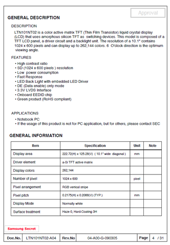
and want to demo the RGB color bar test patternsLTN101NT02-A04-DS.pdf Samsung LTN101NT02 10.1 inch LCD panel with single LVDS interface picture.jpeg on Saamsung 10.1 inch LCD panel with single LVDS interface.
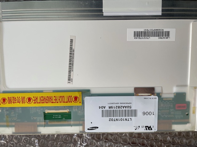
 

Now all of the DC voltages, 27 MHz reference clock, I2C interface looks working as expected.


After running the attached I2C script file from Total Phase USB-to-I2C controller under Windows GUI,

there is no display on the 10.1 inch LCD panel.


Can you help us to check the I2C code to see what's going on?

Can you prove us a working I2C script file to try and compare?


Thanks for the support!


Shane Lee

TI_I2C2.xml TI I2C_2 script file running under Total Phase GUI .pdf SN65DSI85EVM_schematic_RevC.pdf TI SN65DSI85 EVM Re-work list_Rev C PCBA .pdf slla356-SN65DSI85 Trouble Shooting Guide.pdf 


  • Hi Shane,

    Is there successful I2C communication? Can you read/write from the DSI85?

    If so, can you please use the DSI Tuner Tool to enter the display timings (for the Samsung panel) and device configuration to enable and run test pattern. You can download the GUI tool here: SN65DSI83: DSI TUNER tool needed

    Here is a guide to program the DSI85: https://www.ti.com/lit/an/slla332b/slla332b.pdf?ts=1777048144101&ref_url=https%253A%252F%252Fwww.ti.com%252Ftool%252FDSI-TUNER

    Best regards,
    Ikram

  • Hi Ikram,

    Thanks for the update!

    Yes, we can use Total Phase USB-to-I2C adapter and GUI to write TI EVM.

    We have followed TI sample code to generate I2C script file as attached.

    However, there is no color bar being displayed on Samsung / LG 10.1 inch panel.

    Do you know what's the possible reason for that?

    Can you provide me a working I2C script file on your site to compare the test results on TI SN65DSIEVM?

    Thanks for the help!

    Shane Lee

    <aardvark>
    <configure i2c="1" spi="1" gpio="0" tpower="1" pullups="1"/> <i2c_bitrate khz="100"/>
    ======ADDR 0D=======
    ======PLL_EN(bit 0) - Enable LAST after addr 0A and 0B configured======
    <i2c_write addr="0x2D" count="1" radix="16">0D 00</i2c_write> <sleep ms="10"/>
    ======ADDR 0A=======
    <i2c_write addr="0x2D" count="1" radix="16">0A 02</i2c_write> <sleep ms="10"/>
    ======ADDR 0B=======
    <i2c_write addr="0x2D" count="1" radix="16">0B 00</i2c_write> <sleep ms="10"/>
    ======ADDR 10=======
    <i2c_write addr="0x2D" count="1" radix="16">10 20</i2c_write> <sleep ms="10"/>
    ======ADDR 12=======
    <i2c_write addr="0x2D" count="1" radix="16">12 1E</i2c_write> <sleep ms="10"/>
    ======ADDR 18=======
    <i2c_write addr="0x2D" count="1" radix="16">18 72</i2c_write> <sleep ms="10"/>
    ======ADDR 20=======
    ======CHA_LINE_LENGTH_LOW========
    <i2c_write addr="0x2D" count="1" radix="16">20 00</i2c_write> <sleep ms="10"/>
    ======ADDR 21=======
    ======CHA_LINE_LENGTH_HIGH========
    <i2c_write addr="0x2D" count="1" radix="16">21 04</i2c_write> <sleep ms="10"/>
    ======ADDR 22=======
    ======CHB_LINE_LENGTH_LOW========
    <i2c_write addr="0x2D" count="1" radix="16">22 00</i2c_write> <sleep ms="10"/>
    ======ADDR 23=======
    ======CHB_LINE_LENGTH_HIGH========
    <i2c_write addr="0x2D" count="1" radix="16">23 00</i2c_write> <sleep ms="10"/>
    ======ADDR 24=======
    ======CHA_VERTICAL_DISPLAY_SIZE_LOW========
    <i2c_write addr="0x2D" count="1" radix="16">24 58</i2c_write> <sleep ms="10"/>
    ======ADDR 25=======
    ======CHA_VERTICAL_DISPLAY_SIZE_HIGH========
    <i2c_write addr="0x2D" count="1" radix="16">25 02</i2c_write> <sleep ms="10"/>
    ======ADDR 26=======
    ======CHB_VERTICAL_DISPLAY_SIZE_LOW========
    <i2c_write addr="0x2D" count="1" radix="16">26 00</i2c_write> <sleep ms="10"/>
    ======ADDR 27=======
    ======CHB_VERTICAL_DISPLAY_SIZE_HIGH========
    <i2c_write addr="0x2D" count="1" radix="16">27 00</i2c_write> <sleep ms="10"/>
    ======ADDR 28=======
    ======CHA_SYNC_DELAY_LOW========
    <i2c_write addr="0x2D" count="1" radix="16">28 00</i2c_write> <sleep ms="10"/>
    ======ADDR 29=======
    ======CHA_SYNC_DELAY_HIGH========
    <i2c_write addr="0x2D" count="1" radix="16">29 02</i2c_write> <sleep ms="10"/>
    ======ADDR 2A=======
    ======CHB_SYNC_DELAY_LOW========
    <i2c_write addr="0x2D" count="1" radix="16">2A 00</i2c_write> <sleep ms="10"/>
    ======ADDR 2B=======
    ======CHB_SYNC_DELAY_HIGH========
    <i2c_write addr="0x2D" count="1" radix="16">2B 00</i2c_write> <sleep ms="10"/>
    ======ADDR 2C=======
    ======CHA_HSYNC_PULSE_WIDTH_LOW========
    <i2c_write addr="0x2D" count="1" radix="16">2C 88</i2c_write> <sleep ms="10"/>
    ======ADDR 2D=======
    ======CHA_HSYNC_PULSE_WIDTH_HIGH========
    <i2c_write addr="0x2D" count="1" radix="16">2D 00</i2c_write> <sleep ms="10"/>
    ======ADDR 2E=======
    ======CHB_HSYNC_PULSE_WIDTH_LOW========
    <i2c_write addr="0x2D" count="1" radix="16">2E 00</i2c_write> <sleep ms="10"/>
    ======ADDR 2F=======
    ======CHB_HSYNC_PULSE_WIDTH_HIGH========
    <i2c_write addr="0x2D" count="1" radix="16">2F 00</i2c_write> <sleep ms="10"/>

    ======ADDR 30=======
    ======CHA_VSYNC_PULSE_WIDTH_LOW========
    <i2c_write addr="0x2D" count="1" radix="16">30 03</i2c_write> <sleep ms="10"/>
    ======ADDR 31=======
    ======CHA_VSYNC_PULSE_WIDTH_HIGH========
    <i2c_write addr="0x2D" count="1" radix="16">31 00</i2c_write> <sleep ms="10"/>
    ======ADDR 32=======
    ======CHB_VSYNC_PULSE_WIDTH_LOW========
    <i2c_write addr="0x2D" count="1" radix="16">32 00</i2c_write> <sleep ms="10"/>
    ======ADDR 33=======
    ======CHB_VSYNC_PULSE_WIDTH_HIGH========
    <i2c_write addr="0x2D" count="1" radix="16">33 00</i2c_write> <sleep ms="10"/>
    ======ADDR 34=======
    ======CHA_HOR_BACK_PORCH========
    <i2c_write addr="0x2D" count="1" radix="16">34 A0</i2c_write> <sleep ms="10"/>
    ======ADDR 35=======
    ======CHB_HOR_BACK_PORCH========
    <i2c_write addr="0x2D" count="1" radix="16">35 00</i2c_write> <sleep ms="10"/>
    ======ADDR 36=======
    ======CHA_VER_BACK_PORCH========
    <i2c_write addr="0x2D" count="1" radix="16">36 16</i2c_write> <sleep ms="10"/>
    ======ADDR 37=======
    ======CHB_VER_BACK_PORCH========
    <i2c_write addr="0x2D" count="1" radix="16">37 00</i2c_write> <sleep ms="10"/>
    ======ADDR 38=======
    ======CHA_HOR_FRONT_PORCH========
    <i2c_write addr="0x2D" count="1" radix="16">38 18</i2c_write> <sleep ms="10"/>
    ======ADDR 39=======
    ======CHB_HOR_FRONT_PORCH========
    <i2c_write addr="0x2D" count="1" radix="16">39 00</i2c_write> <sleep ms="10"/>
    ======ADDR 3A=======
    ======CHA_VER_FRONT_PORCH========
    <i2c_write addr="0x2D" count="1" radix="16">3A 00</i2c_write> <sleep ms="10"/>
    ======ADDR 3B=======
    ======CHB_VER_FRONT_PORCH========
    <i2c_write addr="0x2D" count="1" radix="16">3B 00</i2c_write> <sleep ms="10"/>
    ======ADDR 3C=======
    ======CHA/CHB TEST PATTERN(bit4 CHA, bit0 CHB)========
    <i2c_write addr="0x2D" count="1" radix="16">3C 10</i2c_write> <sleep ms="10"/>
    ======ADDR 0D=======
    ======PLL_EN(bit 0) - Enable LAST after addr 0A and 0B configured======
    <i2c_write addr="0x2D" count="1" radix="16">0D 01</i2c_write> <sleep ms="10"/>
    =====SOFTRESET=======
    <i2c_write addr="0x2D" count="1" radix="16">09 01</i2c_write> <sleep ms="10"/>
    ======Read======
    <i2c_read addr="0x2D" count="196" radix="16">00</i2c_read> <sleep ms="10"/>
    ======Read======
    <i2c_read addr="0x2D" count="256" radix="16">00</i2c_read> <sleep ms="10"/>
    </aardvark>

  • Hi Ikram,

    Good morning and happy Monday!

    Do you have a chance to review our I2C script file in order to make RGB color bar show up on Samsung 10.1 inch LCD panel with

    single LVDS interface?

    Any comments and suggestions in order to make the color bar test pattern work on the LCD panel?

    Can you help to verify it on your site first in order to isolate the root cause  from SW and HW setup issue?

    We are using the IPEX40 flex cable as the following drawing.

    Will it match with TI test setup?

    Thanks!

    Shane Lee

  • Hi Shane, 

    Please give me till tomorrow to check the script and get back to you.

    Could you also please share the display panel's LVDS timings: Horizontal and vertical active, front porch, back porch, sync width and LVDS clock rate required.

    Best regards,
    Ikram

  • Hi Ikram,

    Thanks for the update!

    The 10.1 inch LCD panel on our test setup

    is the exactly same as the one being used  in TI reference design.

    /resized-image/__size/640x480/__key/communityserver-discussions-components-files/138/pastedimage1777312806986v2.png

    Please let me know if you have any other questions.

    Thanks!

    Shane

  • Hi Shane, 

    The image you sent doesn't have the display timings. Do you have a link to the datasheet?

    - Ikram

  • Hi Ikram,

    Here is the link to the datasheet of the Samsung 10.1 inch LCD panel:

    https://www.beyondinfinite.com/lcd/Library/Samsung/LTN101NT02-A04.pdf

    It is pin-to-pin compatible with LG 10.1 inch LCD panel on TI SN65DSI65 reference design.

    Thanks!

    Shane Lee

  • Thank you Shane, please give me till tomorrow to generate a script for comparison.

  • Hi Ikram,

    It is OK for me to wait for the test results in TI lab until tomorrow.

    Please let me know the proven working I2C script file in TI lab on TI EVM

    once the test setup has been proven working.

    How about the IPEX 40 pin flex cable drawing proven working in TI Lab for me to compare?

    Thanks!

    Shane

  • Hi Shane,

    We currently do not have this display setup to test in the lab. However, I can share the register settings script to generate a test pattern. The DSI Tuner output have been tested before and customers often use it for setting up test pattern and end-to-end video. From our recommendation, the register settings should be okay to generate an output.

    - Ikram

  • Hi Ikram,

    Good morning and thanks for the update!

    Can you share your register settings script file to generate a test pattern?

    What kind of DSI video source board are you using for the end-to-end Video Quality testing?

    Will it work with Qualcomm Snapdragon SoC, such as QCS615 or QCS 8550 SoC ?

    Both of them have dual MIPI_DSI output , can support UHD 4K video display.

    Thanks!

    Shane Lee

  • Hi Ikram,

    Good afternoon!

    Followings are the batch mode log file of Total Phase I2C script running results for your reference.

    There is no color bar show up on the 10.1 inch LCD panel.

    Any idea what's going on?

    Thanks!

    Shane 

    <aardvark>

    <configure i2c="1" spi="1" gpio="0" tpower="1" pullups="1"/> <i2c_bitrate khz="100"/>

    ======ADDR 0D=======

    ======PLL_EN(bit 0) - Enable LAST after addr 0A and 0B configured======

    <i2c_write addr="0x2D" count="1" radix="16">0D 00</i2c_write> <sleep ms="10"/>

    ======ADDR 0A=======

    <i2c_write addr="0x2D" count="1" radix="16">0A 02</i2c_write> <sleep ms="10"/>

    ======ADDR 0B=======

    <i2c_write addr="0x2D" count="1" radix="16">0B 00</i2c_write> <sleep ms="10"/>

    ======ADDR 10=======

    <i2c_write addr="0x2D" count="1" radix="16">10 20</i2c_write> <sleep ms="10"/>

    ======ADDR 12=======

    <i2c_write addr="0x2D" count="1" radix="16">12 1E</i2c_write> <sleep ms="10"/>

    ======ADDR 18=======

    <i2c_write addr="0x2D" count="1" radix="16">18 72</i2c_write> <sleep ms="10"/>

    ======ADDR 20=======

    ======CHA_LINE_LENGTH_LOW========

    <i2c_write addr="0x2D" count="1" radix="16">20 00</i2c_write> <sleep ms="10"/>

    ======ADDR 21=======

    ======CHA_LINE_LENGTH_HIGH========

    <i2c_write addr="0x2D" count="1" radix="16">21 04</i2c_write> <sleep ms="10"/>

    ======ADDR 22=======

    ======CHB_LINE_LENGTH_LOW========

    <i2c_write addr="0x2D" count="1" radix="16">22 00</i2c_write> <sleep ms="10"/>

    ======ADDR 23=======

    ======CHB_LINE_LENGTH_HIGH========

    <i2c_write addr="0x2D" count="1" radix="16">23 00</i2c_write> <sleep ms="10"/>

    ======ADDR 24=======

    ======CHA_VERTICAL_DISPLAY_SIZE_LOW========

    <i2c_write addr="0x2D" count="1" radix="16">24 58</i2c_write> <sleep ms="10"/>

    ======ADDR 25=======

    ======CHA_VERTICAL_DISPLAY_SIZE_HIGH========

    <i2c_write addr="0x2D" count="1" radix="16">25 02</i2c_write> <sleep ms="10"/>

    ======ADDR 26=======

    ======CHB_VERTICAL_DISPLAY_SIZE_LOW========

    <i2c_write addr="0x2D" count="1" radix="16">26 00</i2c_write> <sleep ms="10"/>

    ======ADDR 27=======

    ======CHB_VERTICAL_DISPLAY_SIZE_HIGH========

    <i2c_write addr="0x2D" count="1" radix="16">27 00</i2c_write> <sleep ms="10"/>

    ======ADDR 28=======

    ======CHA_SYNC_DELAY_LOW========

    <i2c_write addr="0x2D" count="1" radix="16">28 00</i2c_write> <sleep ms="10"/>

    ======ADDR 29=======

    ======CHA_SYNC_DELAY_HIGH========

    <i2c_write addr="0x2D" count="1" radix="16">29 02</i2c_write> <sleep ms="10"/>

    ======ADDR 2A=======

    ======CHB_SYNC_DELAY_LOW========

    <i2c_write addr="0x2D" count="1" radix="16">2A 00</i2c_write> <sleep ms="10"/>

    ======ADDR 2B=======

    ======CHB_SYNC_DELAY_HIGH========

    <i2c_write addr="0x2D" count="1" radix="16">2B 00</i2c_write> <sleep ms="10"/>

    ======ADDR 2C=======

    ======CHA_HSYNC_PULSE_WIDTH_LOW========

    <i2c_write addr="0x2D" count="1" radix="16">2C 88</i2c_write> <sleep ms="10"/>

    ======ADDR 2D=======

    ======CHA_HSYNC_PULSE_WIDTH_HIGH========

    <i2c_write addr="0x2D" count="1" radix="16">2D 00</i2c_write> <sleep ms="10"/>

    ======ADDR 2E=======

    ======CHB_HSYNC_PULSE_WIDTH_LOW========

    <i2c_write addr="0x2D" count="1" radix="16">2E 00</i2c_write> <sleep ms="10"/>

    ======ADDR 2F=======

    ======CHB_HSYNC_PULSE_WIDTH_HIGH========

    <i2c_write addr="0x2D" count="1" radix="16">2F 00</i2c_write> <sleep ms="10"/>


    ======ADDR 30=======

    ======CHA_VSYNC_PULSE_WIDTH_LOW========

    <i2c_write addr="0x2D" count="1" radix="16">30 03</i2c_write> <sleep ms="10"/>

    ======ADDR 31=======

    ======CHA_VSYNC_PULSE_WIDTH_HIGH========

    <i2c_write addr="0x2D" count="1" radix="16">31 00</i2c_write> <sleep ms="10"/>

    ======ADDR 32=======

    ======CHB_VSYNC_PULSE_WIDTH_LOW========

    <i2c_write addr="0x2D" count="1" radix="16">32 00</i2c_write> <sleep ms="10"/>

    ======ADDR 33=======

    ======CHB_VSYNC_PULSE_WIDTH_HIGH========

    <i2c_write addr="0x2D" count="1" radix="16">33 00</i2c_write> <sleep ms="10"/>

    ======ADDR 34=======

    ======CHA_HOR_BACK_PORCH========

    <i2c_write addr="0x2D" count="1" radix="16">34 A0</i2c_write> <sleep ms="10"/>

    ======ADDR 35=======

    ======CHB_HOR_BACK_PORCH========

    <i2c_write addr="0x2D" count="1" radix="16">35 00</i2c_write> <sleep ms="10"/>

    ======ADDR 36=======

    ======CHA_VER_BACK_PORCH========

    <i2c_write addr="0x2D" count="1" radix="16">36 16</i2c_write> <sleep ms="10"/>

    ======ADDR 37=======

    ======CHB_VER_BACK_PORCH========

    <i2c_write addr="0x2D" count="1" radix="16">37 00</i2c_write> <sleep ms="10"/>

    ======ADDR 38=======

    ======CHA_HOR_FRONT_PORCH========

    <i2c_write addr="0x2D" count="1" radix="16">38 18</i2c_write> <sleep ms="10"/>

    ======ADDR 39=======

    ======CHB_HOR_FRONT_PORCH========

    <i2c_write addr="0x2D" count="1" radix="16">39 00</i2c_write> <sleep ms="10"/>

    ======ADDR 3A=======

    ======CHA_VER_FRONT_PORCH========

    <i2c_write addr="0x2D" count="1" radix="16">3A 00</i2c_write> <sleep ms="10"/>

    ======ADDR 3B=======

    ======CHB_VER_FRONT_PORCH========

    <i2c_write addr="0x2D" count="1" radix="16">3B 00</i2c_write> <sleep ms="10"/>

    ======ADDR 3C=======

    ======CHA/CHB TEST PATTERN(bit4 CHA, bit0 CHB)========

    <i2c_write addr="0x2D" count="1" radix="16">3C 10</i2c_write> <sleep ms="10"/>

    ======ADDR 0D=======

    ======PLL_EN(bit 0) - Enable LAST after addr 0A and 0B configured======

    <i2c_write addr="0x2D" count="1" radix="16">0D 01</i2c_write> <sleep ms="10"/>

    =====SOFTRESET=======

    <i2c_write addr="0x2D" count="1" radix="16">09 01</i2c_write> <sleep ms="10"/>

    ======Read======

    <i2c_read addr="0x2D" count="196" radix="16">00</i2c_read> <sleep ms="10"/>

    ======Read======

    <i2c_read addr="0x2D" count="256" radix="16">00</i2c_read> <sleep ms="10"/>

    </aardvark>


  • Hi Ikram,

    Good morning !

    Do you have any comments and suggestions on our I2C script file to generate RGB color bar?

    With the current code,

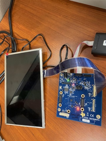
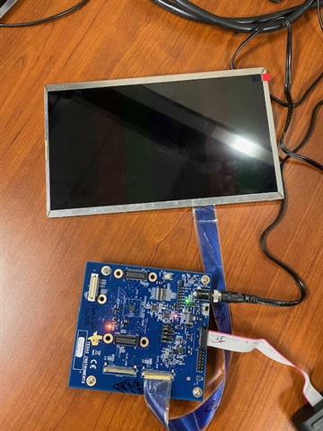
    we can see very dark RGB color bars show up as the following picture

    Any suggestions to make the color bar more brighter as the LED backlight PWM signal  duty cycle has already been set to 100 %

    on TI EVM.

    The Samsung 10.1 inch LCD panel,

    and 40pin IPEX cable are all looking good now.

    Thanks for the support!

    Shane Lee

  • Hi Shane,

    Did you try with different PWM levels? If the pattern it showing correctly then this might just be related to the backlight brightness.

    The test pattern transmission should be okay if the image is showing as expected.

    - Ikram

  • Hi Ikram,

    Thanks for your comments!

    As this is a half standalone test without any DSI source,

    so there are only 2 options for the brightness of the backlight LED: 0% (totally off) or 100% (full on).

    Do you know how to adjust the backlight brightness in this special test case?

    Thanks!

    Shane

  • Hi Shane,

    The LCD panel has a "Power ON/OFF Sequence" for backlight and LED. Could you please check with your setup if it's following that sequence.

    Thank you,
    Ikram

  • Hi Ikram,

    Good morning and Happy Monday!

    I have tried the following re-works on the original TI SN65DSI85EVM,

    1. Move R32 to R33 ( 0 Ohm, 0402 resistor ) to use internal 27MHz clock as reference clock.
    2. Add 6pcs 0 Ohm, 0603 resistor for R94, R95, R96, R97, R98, R38 to use internal BL generator for LCD Panle backlight.
    3. Move R63 = 0 Ohm, 0402 resistor to R37 in order to manually toggle LED backlight Dimmy Control  from the default 0% to 100% (SW2_pin16 GP_DIP).

    Manually toggle SW2_Pin16 GP_DIP on and off and on again seems NOT help for the Dimmy control from 0% to 100%.

    Can you let me know how TI can get the R-G-B color bar much brighter than our EVM?

    What's the detailed step-by-step test setup procedures in TI lab with the same TI EVM?

    Thanks for the support!

    Shane Lee

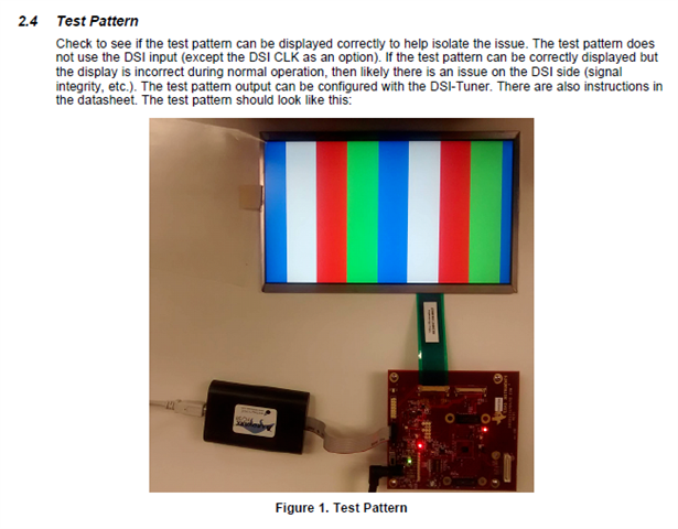
    1. RAVE TI EVM color bard test results in RAVE lab:

    2. TI color bar test results in TI Lab:

  • Hi Shane,

    Please give me till tomorrow to look into these EVM settings and get back to you.

    Best regards,
    Ikram

  • Hi Shane,

    By default the backlight driver should be ON, on the EVM using the TPS61181A device. Did you originally have R63 = 0Ohm populated so that the TPS611 is enabled? That device should be powering backlight.

    Can you also check that LED_EN on SW2 is high so that the J2 LED_EN is set.

    Best regards,
    Ikram

  • Hi Ikram,

    Good morning and thanks for the suggestions!

    I have tried manually toggle

    SW2 DIP1 on-off-on,

    SW2 LED_EN on-off-on,

    SW2 PWMIN on-off-on,

    There is no difference for the Backlight brightness.

    However, manually reset button SW1 looks working as it

    can reset the I2C default settings after manually reset.

    Do you have any live demo of SN65DSI84 end-to-end application

    from DSI video source to LCD panel sink?

    TI bridge chip I2C registers can be controlled by DSI source also, correct?

    Thanks!

    Shane Lee

  • Hi Shane,

    However, manually reset button SW1 looks working as it

    So the backlight issue is fixed and it is working as required now?

    There are examples of this device setup on E2E and on the EVM User's guide: 

    We do not have a full demo currently running to show as a demo, since this part has been in production for 10+ years. Please let us know if you need any suggestions for testing end-to-end video.

    The DSI input will require a cable connection from the SoC. Please check the SoC EVM or DSI generator for a suitable cable connector, or through an adapter to connect to this EVM.

    The CSR, I2C registers on the DSI84 will need to be configured via I2C, not over the DSI input. So, the device still needs to be programmed either from the SoC, or for your test setup, it can be configured with your PC the same way you programmed it for the test pattern generation. You can use the DSI Tuner to generate the script. For the final system, the SoC or local host can write to the device via I2C to program it.

    Best regards,
    Ikram

  • Hi Ikram,

    Thanks for the update!

    The backlight not bright enough issue is still there without any solution yet.

    Do you have any other suggestions to get this issue resolved ASAP?

    Can you help us to duplicate the issue on your site as all of the parts come from TI ?

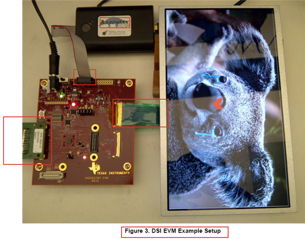
    BTW, can you provide us the detailed info of the Green daughter board of DSI input

    on the left side of the TI setup picture?

    Do you have any datasheet, user guide and reference schematic of this DSI source daughter board?

    Is it ready to be ordered and tested ?

    Thanks again!

    Shane Lee

  • Hi SHane,

    Here is the information I found about the breakout board. It's an adapter for SMA to the Samtec QSH-type connector:

    This is what the Samtec breakout board looks like: http://suddendocs.samtec.com/prints/hdr-128291-xx-mkt.pdf 

    You'll need to get any other additional information from Sametec directly. 

    The DSI source you are trying to use, does it have SMA output or adapter?

    - Ikram

  • Hi Ikram,
    Thanks for the update!
    We have one HDMI-to-DSI EVM from Toshiba with different connector and pin out.
    Can you let me know how TI verify the function from DSI source to dual LVDSL sink end-to-end?
    What's the test setup block diagram and parts list?
    Thanks!
    Shane
  • Hi Shane,

    The system was tested before, it was using a DSI generator with SMA outputs and using the adapter (SMA to Samtec) to connect to the EVM.

    On your setup, it will depend on the type of output you have. If you have DSI generator with SMA outputs, then you can use the adapter to connect to the Samtec input connector. Otherwise, you could use a different connector based on the Toshiba connector pinout. Is there an adapter for your EVM to output SMA?

    You could also use the Hirose FX type input as well.

    Best regards,
    Ikram

  • Hi Ikram,

    Good morning and thanks for the update!

    Do you have any DSI generator with SMA outputs for our design reference?

    Any datasheet ? user Guide ? Reference schematic of this TI DSI generator?

    Can we order 1pcs or borrow 1pcs to test and evaluate with TI SN65DSI85 EVM

    in order to prove the design concept first?

    Thanks for the support!

    Shane Lee

  • Hi Shane,

    The DSI generators are not from TI. I was referring to DSI generators from Introspect, or Teledyne.

    If you do not have a generator/analyzer available, you could use the SoC "HDMI-to-DSI" converter EVM you have as the source. But you would need to use an adapter if you want to connect the EVMs to test end-to-end.

    - Ikram