This thread has been locked.

If you have a related question, please click the "Ask a related question" button in the top right corner. The newly created question will be automatically linked to this question.

True fail safe biasing replacement for SN65ALS180

Other Parts Discussed in Thread: SN65ALS180, SN65HVD55, SN65HVD53, SN65HVD54, SN65HVD1791

The person who designed the logic board for our product used the SN65ALS180 for our RS-485 tranceiver. However, he neglected to include the proper fail saif biasing hardware necessary to impliment a reliable RS485 bus. I have read about some transceivers that are designed with true full fail safe hardware already built in. For example, Intersil has the ISL3150E. Does Texas Instrurments have anything with full fail saife biasing built in?  

Please help me find a replacement for the SN65ALS180. The replacement needs to maintain the same pin assignments and package size of the SN65ALS180 so that I don't have to change the foot print or re-manufacture the PCB. And ofcourse, the replacement would need to have all the necessary fail safe biasing built in to the IC.

Thank you.


  • Joseph,

    what data rate are you using? The SN65ALS180 allows for up to 25 Mbps, the ISL3150 hoever is a 0.115 Mbps device.

    we have 3 speed -grades with internal idle-bus failsafe: SN65HVD55 -> 1 Mbps, SN65HVD54 -> 5 Mbps,  SN65HVD53 -> 25 Mbps

    If it is for your J1708 application I however suggest using the SN65HV1791 with 0.115 Mbps, wide common-mode range of -20V to +25V and 70V robustness, internal failsafe for idle, open, and short bus.  PLEASE SEE DATA SHEET ATTACHED.

    Regards, Thomas

    SN65HVD1791.pdf
  • Joseph,

    I had yet another idea. You said the previous board designer didn't include external failsafe biasing. Note that this type of biasing is often installed at only one node within the bus, normally at one of the two bus ends together with a termination resistor. So before you install another biasing network, please investigate and make sure you do not have some failsafe arrangement any where else unnoticed in the other bus nodes.

    Just a thought of precaution. Regards, Thomas

  • 8547.current_RS485.docxThomas,

    Thank you for your replies. I am really learning a lot from you.

    What I am dealing with is three nodes I would like to connect to an RS-485 Bus. The transceiver for each node is the SN65ALS180 and currently, all three nodes are configured the same. – Please see attached document.  

     I am trying to design the best and most reliable RS-485 bus that I can with a data rate of 115kbs. I need your help with the following items.

    1)      Can I simply use the SN65HVD55 to replace the SN65ALS180 of the first node while leaving the configuration of the SNALS180 as it is in the other two nodes? With  termination resistors at node one and node two?

    2)      What about Grounding issues, noise, and other considerations?


    We want to use a daisy-chain network where the distance between node one and node two is about 40 feet and the distance between node two and node three is about 15 feet.

    Please let me know if you have any recommendations for me to accomplish this task most effectively.

  • Or should I simply replace the SN65ALS180 with the SN65HVD55 at each of the three nodes?

  • To build the most robust RS-485 network you need to know your expected ground potential differences between the individual nodes. If large ground noise where the ground potential of a node can vary by several hundreds of volts, you would need digital isolators in the signal path.

    For low EMI radiation you need a driver with longer rise and fall times such as my previous suggested SN65HVD1791. This device is also better than the HVD55 for common-mode voltages of less than 20V.

    You will need to place you terminations at the bus ends that is Node 1 and Node 3, NOT node 2.

    Of course the proper way is to not put the termination onto the node but have separate "termination plugs".

    You would also need to know your estimated differential noise than could appear on the bus due to noise radtiated by external sources.

    You could further implement a common-mode noise filter using split-termination. In this case you would divide a 120 ohms termination resistor into two 60 ohms resistors and connect a 1nF to 10 nF capacitor from the middle tap of these resistors to the local ground.

    Have you build your board or do you start a new design?

    regards, Thomas


  • Thanks for the fast replay and info.

    To answer your question, the board has already been built and this will not be a new design. I am trying to find out if I can just replace the exisiting SN65ALS180 with either the SN65HVD55 or the SN65HVD1791 at all three of the nodes. Or should I only replace the IC at one of the nodes? The reason I am asking is because you previously mentioned that fail safe is typically only added to one node on the bus.

    Will it cause problems to have node one with the SN65HVD1791 and nodes two and three with the SN65ALS180?

    I am not sure about the ground potential differences or the noise of the environment. I would suspect it to be rather noisy at times. These products will be on a public transit bus and so the noise level will vary depending on the number of passengers and the electronic devices they may be using.

    Thanks, Joseph

  • Sorry, I should have been more detailed in my explanation. Each transceiver on the bus (with internal failsafe biasing) has weak current sources that driver the receiver output to high if there is 0V on the bus. For example the HVD1791 goes already high at -10mV Vid (that is when Va is even 10mV negativer than Vb.

    The failsafe biasing I was talking about is the external version where you use low-impedance biasing resistors. On short buses like yours this should only be done at one bus end. Now I assume that the previous board with the ALS180 already worked and you just want to update the older power hungry devices, with more robust, less power hungry devices. For this you can simply replace the SN65ALS180 with the SN65HVD1791 and things should work fine.

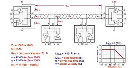
    If you want to increase the failsafe voltage (or idle-bus voltage say to 100mV) use the equations below. If you use a termination resistor at the far end of RT1=120 ohms, and your idle-bus voltage should be 100mV, then your failsafe resistor value calculates to RFS = [4.5V/0.1V +1] x 27.8 ohms = 1.2788 kohms. Choose 1.27k for both RFS resistors.  Then calculate your RT2 via RT2 = 1[1/120 - 1/(2x1.27k)] = 125.95 ohms. Make RT2 = 127 ohms. This should work. Good luck, Thomas

  • Thanks for the additional explanation.

    The reason I want to replace the SN65ALS180, is because the current board design does not include any external fail safe biasing. I was hoping to find an IC that has the appropriate and necessary fail safe biasing already built into it. That way, I can just replace the SN65ALS180 without changing the foot print and without having to re-design the board. I just want to drop a new IC in place of the SN65ALS180 and be done.  It all comes down to the fact that the previous designer never put any fail safe biasing with the SN65ALS180. I am trying to fix his mistake with out having to go through all the trouble of re-manufacturing a new board. I just want to simply replace the SN65ALS180 with an IC that has all the appropriate biasing circutry built into it. I am afraid that the SN65ALS180 will not work in my design without any of the appropriate fail safe biasing.