This thread has been locked.

If you have a related question, please click the "Ask a related question" button in the top right corner. The newly created question will be automatically linked to this question.

TUSB9261: Win & Linux PC's can only see it when no media is connected

Other Parts Discussed in Thread: TUSB9261, TUSB9261DEMO, TUSB9260, LMK00105

A TUSB9261 is connected through a USB 3 hub controller to a PC. At the SATA interface is an eSATAp drive. The circuit used is essentially that of the Evaluation Board, except for the clock which is fed directly, and the reset is provided by a MCP130T-315 reset controller. (see below)

2860.TUSB9261 cct.pdf

In this case only the Rx polarity is swapped, so TUSB926x_FW_v1.00_SATA_POLARITY_SWAP_RX.bin was uploaded to the Flash using the Flash Burner. HID was enabled.

Without an eSATAp drive connected, both Windows 7 and Linux PC's can see the TUSB9261. In the case of the Win PC, "Computer Management" showed it as Disk 1, Removable (H:) No Media

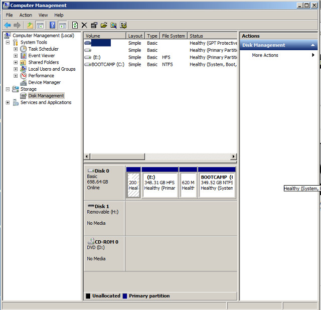
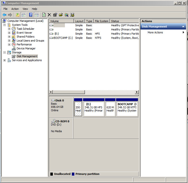
However, when media IS inserted, neither the Win or Linux PC's can see the TUSB9261 any more. In the case of the Win 7 PC:

Regardless of whether the HDD is connected or not, the HDD_ACT led is ON, as is the SS_CONNECT led. While theSW_HB lead is pulsing at ~ 1Hz

The remaining leds are OFF, so the Power state is U0: Active

The milestone for this part of the project in two days away, so I'm getting a little frantic, although it is so very close.

Can you (anyone) please shed some light on this strange behaviour?

  • Hi Errol,

    The TUSB9261 emulates a 'dummy' drive when no SATA device is connected to it, that is why it is enumerating a removable media instance when no drive is connected. The problem seems to be that the TUSB9261 is failing to recognize the drive you are plugging to the device. Are you powering externally the device? Is it possible for you to try connecting a different SATA device to your TUSB9261 implementation to check if it enumerates properly? When testing, please program the TUSB9261 without UAS and HID.

    Also, do you have a TUSB9261 demo board at your end? If so, could you please try connecting the failing eSATAp drive to it (you will have to use the default firmware, no polarity swap firmware) and see if it enumerates. 

    Could you please provide the model of the eSATAp device you are using?

    Best Regards,

    Alexis Cortes.

  • Thanks for the speedy reply Alexis.

    Are you powering externally the device? Yes

    Is it possible for you to try connecting a different SATA device to your TUSB9261 implementation to check if it enumerates properly?

    I have tried two eSATAp devices :-

    Addonics CFast Card Reader (http://www.addonics.com/products/adespcft.php)

    and a hard drive that I can not name.

    I have also tried a SATA drive, OCZ Technology, VTR1-25SAT3-256G, powered separately by an ATX supply (GN wire to BK to switch it on)

    None enumerate

    When testing, please program the TUSB9261 without UAS and HID

    No success with any of the following combinations:-

    No UAS and No HID

    No UAS but HID checked

    Both UAS and HID checked

    UAS checked and no HID

    Also, do you have a TUSB9261 demo board at your end? Unfortunately NO. (On reflection this would have been a very good purchase)

    I have now managed to get another board running, and it exhibits the same behaviour as the first. Given that 3 SATA devices aren't seen by the chip, I suspect a design fault. Perhaps there is a wiring fault from the TUSB9261 to the eSATAp connector? I can't see it though.

  • Further to the possible wiring error, I've read that the capacitors should be mounted on the rear of the board and adjacent the connector, presumably to limit "stubs". This was not done on our board.

    The caps are on the top layer and the Tx lines continue on the top, while the Rx lines drop down two layers (of 8), and continue to the pin at that level. So in the case of the Rx lines, there are two stubs, one at the via, and the other at the connector pin. The Tx lines have one stub at the connector pin. The following cross-section of the Rx path should illustrate it.

    Is this likely to be the cause of the problem?

    (PS. A demo bd was ordered today)

  • Hello Errol,

    The stubs on SATA_RX definitively needs to be minimized, however having those stubs would cause data errors not unreachable link. Can you take some scope capture of the SATA lines to see the signal quality?

    The schematic has one error: Terminal USB_VBUS should not be connected to 1.1V. If the TUSB9261 is going to be actively attached/detacched from the USB host, USB_VBUS shall be connected to VBUS using a voltage divider (See Implementation guide at http://www.ti.com/litv/pdf/slla315d). If the TUSB9261 is going to be in an embedded application where it will be always connected to the USB host, then USB_VBUS can be connected directly to a voltage source, always following the voltage divider implementation which provides a 0.5V to this terminal.

    The schematic does not show the connection from the TUSB9261 to the USB Host, make sure you have the AC coupling capacitors on the USB_SSTX lines of the TUSB9261.

    Regards.

  • Errol,

    Additionally, please let us know your test results using the TUSB9261 demo board once you have it.

    Best Regards,

    Alexis Cortes.

  • Can you take some scope capture of the SATA lines to see the signal quality?

    Unfortunately I don't have access to a scope fast enough to capture it. 100MHz is our limit.

    2703.TUSB9261 cct.pdf

    The link above shows a little more. There are caps on the USB_SSRX lines to the hub, but none on the USB_SSTX lines. The hub is on a different page in the main documents, so I (and two others) missed it. Mind you, "TUSB9261 Burner" didn't mind, but my test PC only has USB2, so maybe that is the reason.

    The TUSB9261 enumerates without a SATA device connected, so that would suggest that the USB biases match, and the caps aren't needed in this case. (Fair assumption?)

    I subsequently lifted the USB_SSTX legs, cut the traces to their pads so that they didn't act as stubs, then placed 22pF (0201) caps between the raised legs and the arriving traces (that was fun). It made no difference though. The chip still enumerates without a SATA device connected, and will not enumerate with one connected.

    Another wrinkle: I've used 10nF caps instead of 100nF for the coupling caps on the SATA lines. I wouldn't expect that this would be a problem though. 10 pF would probably be enough at 600MHz - 6GHz (22pF was fine for USB3 above), or perhaps there is more to it than that?

    As far as the VBUS voltage divider is concerned, the system is self powered, and always connected to the host, so I assumed that, provided that 1.15V was not exceeded, all would be well. The 1V1 supply is actually 1.101V

  • Errol,

    I don't think the issue is on the USB side, since you are saying that it is properly enumerating (no yellow bang on dev manager?) and also because you are successfully programming the flash with the FlashBurner tool.

    When do you expect to have the TUSB9261 Demo board? Using your drives with the demo board will help us no narrow down the issue.

    Have you verified the disks you are using work fine by connecting them directly to an eSATA port or to another USB to SATA bridge?

    Best Regards,

    Alexis Cortes.

  • no yellow bang on dev manager?

    No, it's fine.

    When do you expect to have the TUSB9261 Demo board?

    I expect it to arrive Friday or next Monday

    Have you verified the disks you are using work fine by connecting them directly to an eSATA port or to another USB to SATA bridge?

    Yes. We have an Addonics USB3.0 to eSATAp dongle. All of the drives I have used for testing have worked fine on that.

    Tomorrow I plan to drill out the stubs on a mini CNC mill and see if that helps.

  • let us know your test results using the TUSB9261 demo board once you have it.

    The board arrived Friday, and it works fine with a SATA drive.

    Over the weekend I modified an eSATAp to CFast interface to use as SATA - eSATAp. On plugging an eSATAp drive into that combination, directly to a PC, I found that it works fine as well. Although, curiously, the TUSB9261DEMO does NOT enumerate without a drive connected.

    I have just now connected the TUSBDemo/SATA - eSATAp combination to my circuit, which has a USB3 hub on it, and it works fine. The TUSBDemo will be seeing the same hardware as the TUSB9261 sees, so that eliminates any device incompatabilities.

    That leaves the physical wiring from the TUSB9261 to the eSATAp connector.

  • Hi Errol,

    As you mentioned on your post, we can rule out then probable compatibility issues between the TUSB9261 and the SATA/eSATAp devices you are using. One question here: Did you test in both USB3 and USB2?

    Regarding the 'not enumerating' issue you found when no SATA device is attached to the TUSB9261Demo board: Did you update the TUSB9261 firmware with the latest available on TI's website? It could be that an older version of the firmware is loaded on the shipped boards which behaves differently than the latest one.

    Is it possible for you to send you board's layout so we can take a look at it and see if that helps to find a solution?


    Best Regards,

    Alexis Cortes.


  • G'day Alexis,

    Did you test in both USB3 and USB2? Yes. No difference, except the PC popped up a window saying that it could run faster if a USB3 port were used

    Did you update the TUSB9261 firmware with the latest available on TI's website? No. I will give that a shot tomorrow, but I believe the DEMO boards have proven that it is not the eSATAp hardware I've been testing with is not the issue.

    Is it possible for you to send your board's layout so we can take a look at it and see if that helps to find a solution? Sure. The areas of interest follow. Hopefully screen shots will suffice.

    The layer stack is as follows

    The full screen shot set, zipped, including internal planes is :-

    5460.eSATAp.layout.zip

    The top layer

    MidLayer1

    MidLayer2

    and Bottom Layer

    a composite shot

    The eSATAp connector mounts on the top, so the signals will have stubs because the traces are on the top and mid layer 1, as per my post of Jul 29 2013 06:38 AM.

    The two vias on C72 & C73 will also have stubs

    I drilled out these stubs on a small CNC mill, to the nearest I was game. The connector signal pins were trimmed to effectively surface mount. The traces are still intact, but it made no difference.

    Unrelated but interesting nonetheless - while searching for the fault, I mentioned on Jul 30 2013 23:48 PM that I had cut the SSTX tracks adjacent the TUSB9261 and installed 100n 0402 coupling caps. The USB ceased to operate.

    On one board then, I replaced the 0402's with 22pF 0201's and the USB operated again.

    On the other board, I removed the 0402's and placed a sliver of 30AWG wire, slightly flattened, to bridge the cut track. They were wider than the IC legs, and thicker. It failed.

    I then removed the wire, bridged the cut with solder and trimmed it to roughly the original dimensions using a #11 scalpel. It worked again.

    This proved to me how precise the USB3 circuits must be to operate. SATA is faster still, so I still suspect that the surgery done on one board, to remove the stubs was not precise enough.

  • Hi Errol,

    Sorry for the delayed response, we are still reviewing this and we'll reply soon!

    Best Regards,

    Alexis Cortes.

  • Hi Errol,

    We made a quick review to the images you attached of your layout and I have some comments (From the Top Lager image):

    1. I can see that each SATA differential trace from the TUSB9261 to the coupling capacitors (SATA_TX_N/SATA_TX_P and SATA_RX_P/SATA_RX_N) differ in routing. Did you make sure that those differential signals are of equal length or the mismatch is less than 2.5 mils?

    2. SATA.T_N and SATA.T_P traces are routed with an angle when connecting to the coupling capacitors. It would have been better if those traces were straight (just a thought). For this:

    3. The separation of the SATA coupling capacitors could’ve been reduced.

    Besides those comments/observations, I couldn’t find anything else from your layout's images you attached. So regarding the SATA lines routing, basically if you followed the recommendations of the ‘TUSB9260 Implementation Guide' (section 4.1) (http://www.ti.com/lit/an/slla301c/slla301c.pdf) there shouldn’t be any issues at least on SATA part.

    Please let me know your thoughts.

    Best Regards,

    Alexis Cortes.

  • Hello Alexis,

    we haven't forgotten about this problem, it's just been shelved while other parts of the board were addressed. There has been a lot of discussion about it though.

    As regards your three points:

    1 & 2. the mismatch on each pair is zero from the caps to the connector, but from the IC to the caps is woeful. The angling has given us a 0.125 mm mismatch (4.9 mils) If we change to 0201 caps and place them on the bottom side we can correct that.

    3. 0201 caps will improve this

    Other points raised amongst our group:

    1. Each capacitor pad has a ground plane only 0.152 mm below. This will create an 0.066pF capacitance to ground at each pad, reducing the impedance. We aim to put a plane cutout under these pads

    2. similar to 1., but for each high speed TUSB9261 pad

    3. There is a stub under each of the pins of the TUSB9261 due to the positioning of the pins on their pads. This stub is between 0.7 mm and 1.7 mm, depending on the vagaries of the TUSB9261 S-QFP--G64 package and our choice of footprint. We plan to change our footprint to reduce the stub variation from 0 to 1mm

    4. All bypass caps are on the bottom of the board and therefore in series with inductive vias. We plan to move as many as possible to the top, as close as possible to their respective supply pins.

    5. We will remove via donuts on the middle layers where not needed, to reduce capacitance

    6. We will use antipads adjacent to the SATA differential lines, in an attempt to maintain impedance as it tracks from the top to the bottom of the board

    7. The clock jitter is to be checked

    8. The capacitors will be moved to the bottom of the board to eliminate via and connector pin stubs

    What are your thoughts?

    Would it be possible to get the gerber files for the Demo board so that we can confirm our layout?

  • Hi Errol,

    Please send me an e-mail to alexis.cortes@ti.com so I could send you the gerber files.

    Best Regards,

    Alexis Cortes.

  • Hello Alexis, et.al.

    I've tried various things in an attempt to get this running, to no avail.

    25MHz clock: no overshoots. 1.8Vp-p. Rise and fall times of 5ns. It's clean. It is created by an LMK00105 which has a maximum jitter of 30 fs. Well within the TUSB9261 requirement.

    Supply Bypassing: 100nF direct to the pin where possible on both the 3.3VA and 1.1V lines as per the following.

    Using a Rigol 200MHz CRO, I've measured the 3.3VA and 1.1V noise at under 15mVp-p.

    I've used a potential divider on the Vbus pin to reduce the voltage from 1.1 to 0.497V

    On the SATA side, I've replaced the 0402 decoupling caps with 100nF (didn't have 10nF) 0201's and cut traces from the existing pads in an attempt to reduce the length mismatch.

    My calcs show that the mismatch is now down from 125 um to 61.5um (1.7mils). Practically, I believe it to be better than 2.5 mils, but can not measure it.

    On the Tx side, I drilled out the connector pin plate through barrel to leave the top annulus. The connector Tx pins were cut off level with the top layer and bent out to meet the annulus. The rest of the annulus was cut off to leave an arc. With this mod, the stubs are reduced to zero.

    (It's a bit hard to see what I did, but you can see where I did it)

    On the Rx side, I removed the vias to the inner layer traces from the decoupling caps, and removed the connector plate through holes and annulii. The connector pins were shortened and bent to touch the top surface. The receive connection was then completed with a small loop of 100 Ohm twinax. This reduced the stubs to zero.

    With all of this work, still no joy.

    I have buzzed out the lines from the decoupling caps to their respective points on a remote eSATAp device and confirmed that the hardware connections are correct. I've also checked the same lines from the demo board, to cross check.  The fault doesn't lie there.

    I have seen activity on the Tx traces using a 200MHz CRO, but haven't been able to connect the Tektronix DSA72004 digital serial analyser we have on loan. When it becomes available, I plan to look at both the Tx and Rx signals on an eSATAp-CFast bridge. I will then be able to compare the signals when connected to my circuit and the Demo board.

    Other than the last point, I think I've covered all of the bases. The only real difference between the demo board and mine is the configuration. It swaps the Tx plus & minus lines, only, whereas mine swaps the Rx plus & minus lines, only. I'm starting to suspect the firmware.

    Has anyone used "TUSB926x_FW_v1.02_SATA_POLARITY_SWAP_RX.bin" with success?

  • Hello Alexis,

    in desperation, a cable was modified that swapped the polarities of both Tx and Rx. Then the TUSB9261 was programmed with TUSB926x_FW_v1.02_SATA_POLARITY_SWAP_TX.bin, that used in the demo board.

    IT WORKS!

    What I need now is a version of TUSB926x_FW_v1.02_SATA_POLARITY_SWAP_RX.bin that works.

    Please.

  • Hi Errol,

    Good to know that you managed somehow to make it work.

    How exactly are you connecting the modified cable to the TUSB961? In your original design, are you swapping the SATA RX lines only?

    What it seems weird to me, as you described, is that the modified cable has TX and RX lines swapped and you got the TUSB9261 to work with the binary intended only for 'TX polarity swap' while you should have used the 'swap both' binary.

    Without using the modified cable, could you try all the binaries for each SATA lines combination and see if one of those works for you.

    Best Regards,

    Alexis Cortes.

  • Hello Alexis,

    I had tried all four versions of the firmware with no success.

    My board has Rx polarities swapped, and the modified cable has both Rx and Tx polarities swapped. When connected to my board, Rx is swapped twice, and Tx once, making my board look functionally like the demo board, allowing me to run the demo board firmware. Which we know works fine.

    This leads me to believe that TUSB926x_FW_v1.02_SATA_POLARITY_SWAP_RX.bin is faulty.

    You could try this yourself by making a cable just like my modified one. Plugging that into the demo board would require the use of TUSB926x_FW_v1.02_SATA_POLARITY_SWAP_RX.bin. I think that you will find that it will fail to operate.

  • Hi Errol,


    There's a newer version of the firmware already available at TUSB9261's website. Could you please try this newer version?

    http://www.ti.com/litv/zip/sllc416j

    Best Regards,

    Alexis Cortes. 

  • Hello Alexis,

    just tried v1.03, the latest, and the swap Rx version does not work with a standard SATA cable.

    The swap Tx version DOES work with my modified cable, which effectively makes my board physically the same as a demo board.

    So I still suspect a problem with the swap Rx firmware, at versions 1.02 and 1.03

  • Errol,

    Please try the attached FW.   Wrong compile option was used so Rx polarity wasn't properly swapped.  Sorry for the inconvenience.0434.TUSB926x_FW_v1.03a_setup.zip


    Regards,

    Brian

  • Thanks Brian. I tried installing the new file set. The v1.03a bin and hex files were extracted, but in doing so, I had to accept the un-installation of the v1.03 flash burner. Problem is, there doesn't seem to be a v1.03a flash burner packaged in the file set, so I was left without a burner. I can install the old burner onto another PC and transfer the new files, but at the time, I was 800 kms from my second PC, so it will have to wait now until Tuesday when I get back to the office.

  • That's strange.  The installer should not touch flashburner.  I ran it myselft and it only uninstalls old FW binaries.

    Regards,

    Brian

  • I copied the v1.03a firmware to storage and re-installed the flash burner, then flashed an unmodified board with

    TUSB926x_FW_v1.03a_SATA_POLARITY_SWAP_RX.bin

    and the problem is solved.

    Thanks to all who have helped with this issue.