


Hello,
Following is my system block and my purpose is to use TLK10022 to mux four independent 2.5Gbps LS into one 10Gbps,then back to FPGA.
PRBS15 generator and checker in FPGA will calculate BER of four channel.
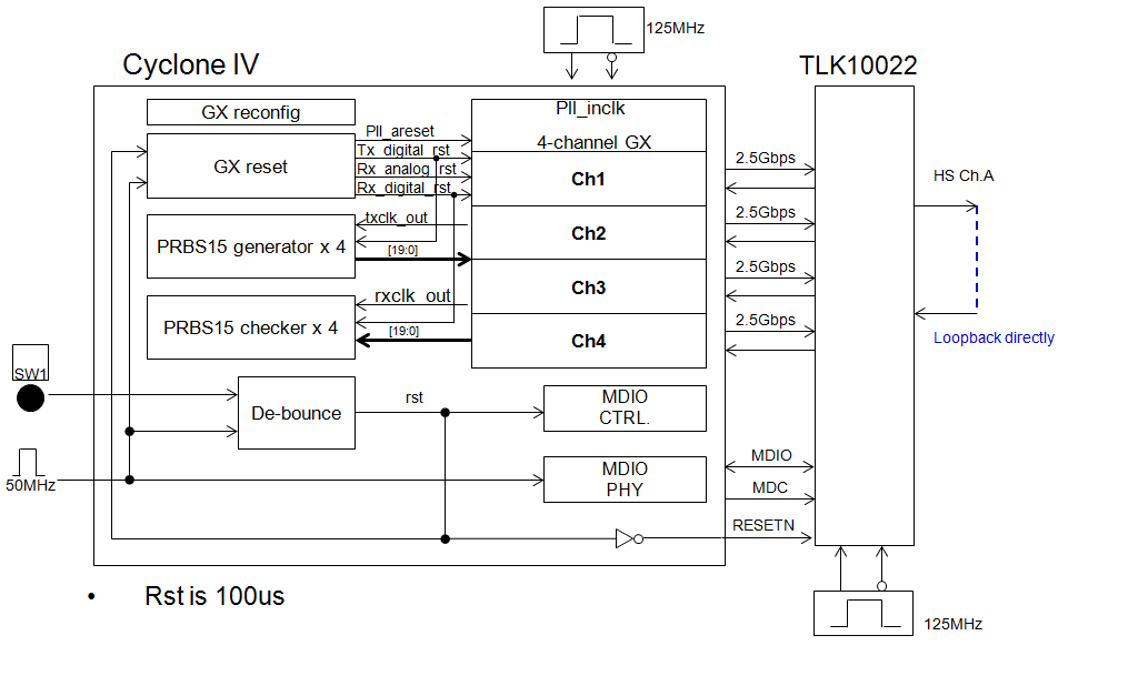
Choose one 20-bit PRBS15 data as sync pattern in Cyclone IV,so I think TLK10022 can operate in raw serial data mode and some registers configuration as following
1) write
reg_addr <= 5'b00000;
mdio_wr_data <= 16'h8610;
2)write
reg_addr <= 5'b00001;
mdio_wr_data <= 16'h4300;
3)write
reg_addr <= 5'b00110;
mdio_wr_data <= 16'h8119;
4)write
reg_addr <= 5'b00111;
mdio_wr_data <= 16'hDD05;
5)write
reg_addr <= 5'b11100;
mdio_wr_data <= 16'h00C0;
6)write
reg_addr <= 5'b11101;
mdio_wr_data <= 16'h088C;
7)write
reg_addr <= 5'b11110;
mdio_wr_data <= 16'h8009;
8)write
reg_addr <= 5'b11111;
mdio_wr_data <= 16'hFC03;
9)write
reg_addr <= 5'b11110;
mdio_wr_data <= 16'h8019;
10)write
reg_addr <= 5'b11111;
mdio_wr_data <= 16'hFC03;
11)write
reg_addr <= 5'b01110;
mdio_wr_data <= 16'h0008;
12)read
reg_addr <= 5'b10011;
value is 0x0000,To check the CTC FIFO status
13)write
reg_addr <= 5'b00110;
mdio_wr_data <= 16'h9119;
14)read
reg_addr <= 5'b10011;
value is 0x0000,To check the CTC FIFO status
15)write
reg_addr <= 5'b00110;
mdio_wr_data <= 16'hA119;
16)read
reg_addr <= 5'b10011;
value is 0x0000,To check the CTC FIFO status
17)write
reg_addr <= 5'b00110;
mdio_wr_data <= 16'hB119;
18)read
reg_addr <= 5'b10011;
value is 0x0000,To check the CTC FIFO status
19)read
reg_addr <= 5'b01111;
After receiver is trained and ready to receive data,transmit one sync pattern for alignment.But in real,some un-predictable data comes out from LS RX and no sync patten found after resonable period.
My question is
a)How to config TLK10022 to De-mux data to the corrent lanes respectively ?
b)Where the un-predictable comes from ? Can we make TLK10022 LS just output parallel PRBS data ?
c)Is the register writing sequence corrent ? Need to optimize ?
In this case,channel B is power down by PDTRXB_N pin.
Thanks.
