This thread has been locked.

If you have a related question, please click the "Ask a related question" button in the top right corner. The newly created question will be automatically linked to this question.

TLK10232 USB Dongle MDC MDIO

Other Parts Discussed in Thread: TLK10232, TLK10232EVM

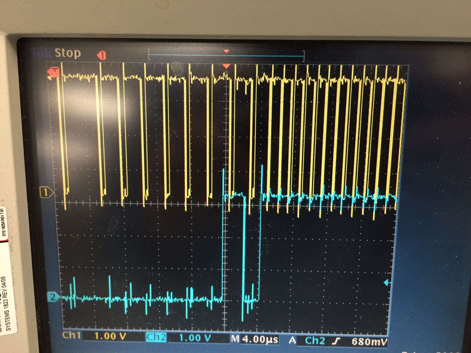
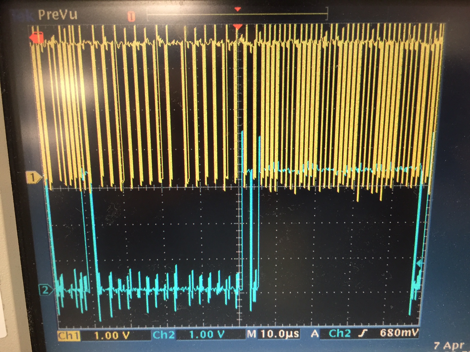
Below are screenshot of the MDC and MDIO signals from the USB Dongle from the TLK10232 Development kit.  I am having issues talking to the TLK10232 and want to verify that the mdc and mdio signals are correct.  The MDC clock doesn't look periodic with 50% duty cycle.  Is this okay?

  • Hi Thao,

    Are you trying to connect the USB dongle from the TLK10232EVM kit to your own board which includes the TLK10232 right?

    As well, since the MDIO protocol requires pullup resistors, there may be a conflict of having pullup resistors on the dongle and on the system board.

    The pullup issue won´t have an impact on the GUI recognizing the hardware, they might have issues with the MDIO communications as a result of the pullups.

    Best Regards,

    Luis Omar Morán Serna

    High Speed Interface

    SWAT Team

  • Correct.  I'm connecting the USB dongle to our board with the TLK10232.  We're going through a bidirectional level shifter to get to the 1.8V I/O on the TLK10232.  The plot I've attached is only the usb dongle with nothing else attached.  Does the MDC look correct?

    Thao

  • Please let me talk with the team who designed the USB dongle for this device, in my understanding the plot is a little strange. I will be back with the answer.

    Regards,
    Luis
  • Hi Thao,

    It can be a little tricky connecting the MDIO/MDC signals to a second board and something I fought on many occasions. There are a couple of different common issues they need to be aware of that are common problems.

    First I see that there is a small amount of crosstalk from the MDIO onto the MDC and vice versa. This usually isn’t the biggest concern, but if it is possible to minimize this, it can only help.

    The biggest problem is the creation of reflections in the signal due to a total signal path length that causes the signal to behave like a transmission line. The MDIO and MDC signals are of open drain architecture and are not terminated in any way. If the total trace + cable length exceeds the distance where round trip distance of the signal exceeds the lambda/2 value, a reflection will occur and result in the double edges they are seeing. I don’t remember exactly how much trace length the EVM has, but let’s assume it is about 12 inches between the USB Dongle and the output header. Then there is obviously some trace length on the customer’s board which I don’t know the length. However, if using a second EVM as a reference, there is another 12” of trace length. Then the cable length between the two boards must be included. I was able to use a ribbon cable of no longer than 2 feet to create stable communication. However, the quality of the cable, the connectors, the number of the stubs on the traces, etc. all will contribute to the maximum trace length and whether any reflections do to other factors are observed. I would suggest that they try to shorten the overall length of the signal path if possible.

    Other techniques I’ve had to do with these is add a series resistor in the path to dampen any reflections that I can’t fully eliminate. For example changing one of the 0 ohm resistors to a 33 ohm resistor might help dampen a reflection. But, I have found that which particular resistor is adjusted and the value of the new resistor can vary on the specific setup. The basic problem that needs to be overcome is the use of the bi-directional level shifting IC. Because it is auto-senses the direction it has some difficult VIL and VIH levels that require a fairly clean signal. If it sees a reflection on the slave side that exceeds the VIH/VIL trip points, then the level shifter will change direction and corrupt the data . Adding the dampening resistor can help reduce the reflections, but also prevent the normal signal from reaching the VIH/VIL trip points, so this really becomes a trial and error balancing game. One other issue that can come about by this level shifter is the value of the pullup resistor on the MDIO/MDC lines. I found that using a 4.02k pullup resistor worked well using evm boards, but that the level shifter wouldn’t function with a 2k as is typical in a system application.

    Also, make sure there is only one level shifter in the signal path. If the customer is using a level shifter in their system, and we also have one on our evm, then the two may not be compatible in series. When I use two evms, I have to bypass one of the level shifter on the second board so that it works. Perhaps this is also needed in the customer’s setup.

    Otherwise, adding a very small cap (a few pF’s) on the MDIO/MDC could also help smooth out the signals, but this is just a final option to help tune the setup in an analog fashion.

    Also, I am assuming they already did this, but make sure the PRTAD address of the EVM TLK device is different than that of the address used on the customer’s system.

    I hope this information helps.

    Best Regards,
    Luis Omar Morán Serna
    High Speed Interface
    SWAT Team
  • Thanks Luis. The screenshot I took was just from the usb dongle, which was not attached to a dev kit. The stub is probably less than an inch from the ic to the edge connector. We installed a pullup resisters of 4k on usb dongle on these lines, since the dongle had them as unpopulated. I also probe it at this pullup and MDC looks that same.

    Thao
  • Hi Thao,

    1. Do you have anything connected to the USB dongle (any load)? Or are you just measuring to the MDC and MDIO signals in the USB dongle connected to the PC?

    2. Also, have you tried with another probes? Is posible there is an issue with hook up.

    Best Regards,

    Luis

  • There is no load on the lines besides the pullup resistors. I have tried one other probe. I can switch over to a different scope and probe.
  • Hi Thao,

    Do I understand you correctly in you are trying to wire the USB dongle directly to your board and not run it through the TLK10232 EVM first?  If you are doing this, then you must use a bi-directional level shifter on their application board because the USB MCU signals are 3.3V levels and the TLK10232 requires the 1.5V or 1.8V levels depending upon their board configuration.  If you do not have a bi-directional level shifter in the signal path between the USB MCU and the TLK10232, then the signal levels alone will prevent any MDIO communication.  Is there a way we can get a schematic, picture, and or diagram of your setup to provide a better feedback?


    Best Regards,

    Luis Omar Morán Serna

    High Speed Interface

    SWAT Team