This thread has been locked.

If you have a related question, please click the "Ask a related question" button in the top right corner. The newly created question will be automatically linked to this question.

RS-485 IC inputs need pull-ups?

Other Parts Discussed in Thread: SN75HVD07, SN65HVD10

Hi,  I have been using the MAX485 IC break-out that most Arduino noobs like myself encounter.  As you can see in the schematic all the IC inputs (D, DE, RE, R) have 10K pull-ups.  I connect DI to TX, and RO to Rx of serial uart pins of my Arduino, and some other random digital pin is connected to DE and RE : OUTPUT LOW to enable driver, and OUTPUT HIGH to enable receiver.

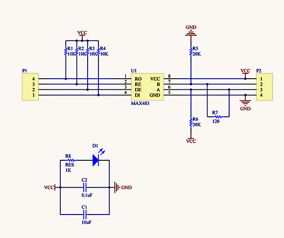
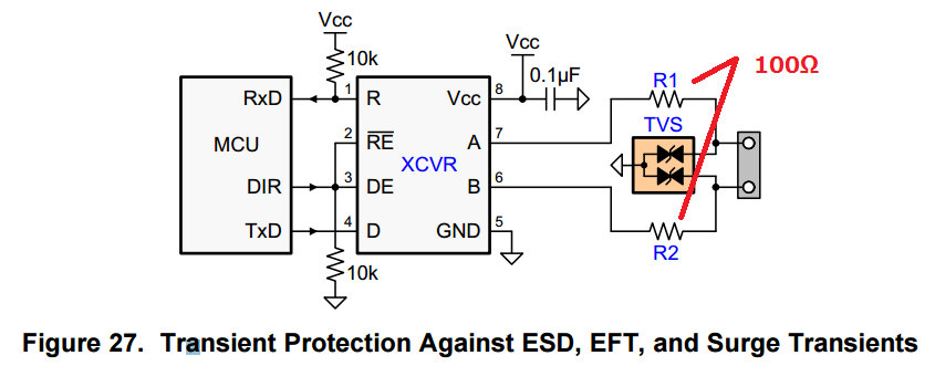
I don't understand why the pull-ups are necessary, or at least present on the break-out board.  I want to use TI chip SN75HVD07 which has the same SOIC8 pin-out as the MAX485 chip but I don't know if the pull-ups should be used or not.  I notice in another recent post on this forum "SN65HVD10 TVS Application"  that his schematic has a pull-up on D, but pull-downs on all the rest. See below:

Can someone advise me as how to implement the SN75HVD07 chip in regards to pull-up/down resistors if I connect the inputs to the serial Tx/Rx pins on my arduino? 

FYI, I want to use the SN75HVD07 chip because I have an application that needs over 100 drops on several kilometers of  telephone cable.  I think this chip requires less fail safe loading than the max485, if any at all, and thus I will be able to get the number of drops I need.  Also, It appears to me that the 07 chip is the low slew rate version of the family which would be most tolerant of the crappy cable. I don't mind slow transmission rates because I don't have much to say, and it's necessary any way because of the extreme cable length.  As in "old mates" schematic below, I would also like the extra protection of a TVS diode array, (with 10Ohm resistors of course), but don't know if the extra 75pF per drop, and 10Ohm resistors will impinge on me being able to have more than 100 drops on the bus. Any one kind enough to impart their wisdom? Cheers, Matt.

  • Hi Matthew,

    The pull-up and pull-down resistors are not required. They are just used so that the state of each pin on the RS-485 transceiver is defined even when the MCU is powered-down, disabled, etc. If this is not a concern, you can simply connect the MCU outputs directly to the transceiver.

    The additional TVS diodes and resistances on the bus aren't likely to limit the number of nodes. In terms of frequency response, 100 diodes at 75 pF/diode would add 7.5 nF to the bus. Coupled with the 10-Ohm series resistance, this would create a low-pass filter with corner frequency > 2 MHz at the driver output. The HVD07 output rise/fall times are slow enough that this wouldn't have much of an effect besides maybe a little roll-off of the edges. (It's an oversimplification to look at this circuit just as a single-pole filter since longer cables will introduce transmission line effects as well, but this should be an accurate enough approximation to determine whether there would be significant issues.)

    Another thing to check when adding components to the bus is the additional DC loading they create. An RS-485 driver is designed to support a terminated bus with up to 32 "unit loads." (The low leakage current of the HVD07 device means that it only acts as 1/8 of these unit loads, allowing for 256 nodes to be supported.) As long as the leakage of the TVS in its stand-off region (prior to the reverse breakdown voltage) is low (<100 uA) then you shouldn't have issues supporting ~100 nodes.

    I hope this is all clear; please let me know if you have any questions.

    Regards,
    Max
  • Am I right in thinking that only one transceiver on the bus can have its driver enabled at any one time without transmissions being masked?? A bit like radio transmitters, where simultaneous transmissions garble each other? i.e. if an erroneous transceiver was DE/RE low, the bus would not be available to other transmitters? If so a pull-up on the DE/RE would be a good precaution in the unlikely scenario that a slave board was live but the MCU was US/corrupted.


    I'm an aircraft mechanic, and once I shorted the the "press to talk" of a microphone jack to ground with a screw when installing trim. My boss flew all the way to Brisbane with his carrier live. No one else could use the frequency, but the funny bit was that my boss is a deviant, and control heard his entire conversation.

    Thanks again or your help.

    Matt.
  • Matt,

    Thanks for sharing that story - I got a kick out of it.

    You're right that you need to ensure that only one driver is active on the bus at a given time. Otherwise, you run the risk of bus contention, in which one driver is trying to drive high while another drives low. The end result would be voltage levels that aren't fully "high" or "low" and could thus be interpreted by a receiver in unpredictable ways. You also end up making the drivers source larger currents as they act against one another. Unlike with radios, you wouldn't have the option of hopping to a different frequency, either, so the situation would be especially bad.

    Most RS-485-based links use transmission protocols that avoid this issue (for example) by imposing a master/slave hierarchy, by implementing token passing, or by giving each node a defined time slot to transmit their data.

    Max
  • Thanks Max, very kind of you to take the time to help.

    Cheers

    Matt.