This thread has been locked.
If you have a related question, please click the "Ask a related question" button in the top right corner. The newly created question will be automatically linked to this question.
We have purchased PCA9306 for i2c level shifting, and also used basic mosfet level shifting. In our application it does not work, and we don't understand why. I wonder if you can guide us a bit, into understand why PCA9306 is re-acting this way, and if there is possibly a newer/better chip that you would recommend.
The MCU is 3.3v, and the i2c EEPROM needs to work with 5v. We are trying to use the level shifter to convert from 3.3v on MCU side to 5v on the EEPROM side. Our cables are about 3 meters, and their line capacitance are about 100pF. The MCU is atsam3x8e. We cannot change the EEPROM nor the MCU, but we are open otherwise.
1. We need to be able to use i2c for this system. Both MCU, and EEPROM side boards can be modified at this point. However, the EEPROM side should be kept as cheap as possible as it is a consumable.
2. In a secondary situation separate from the first one, we need to be able to make this work with legacy boards on the EEPROM side. They do not have any pull-up resistor on that side, while there is a 3m cable.
What works: When we use a diode-based design, which basically works at 3.3v on one side, and about 4v on the other side, we can make it work. I do not understand why a reasonably standard level shifter, though, doesn't work properly. We have also tried different pull-up values in a range of 1k-10k, and for the sake of testing, we are trying speeds as low as 10kHz, so that a fast pull-up is not required, however, our minimum requirements after we fix this problem would be the standard 100kHz speed.
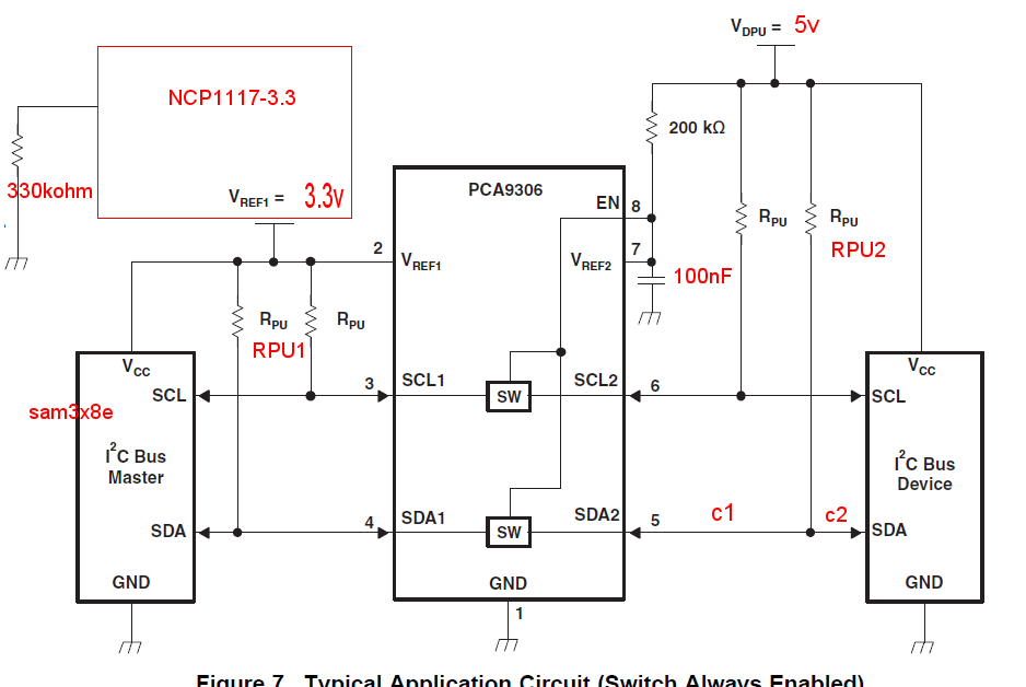
Schematics is provided below. Many situations are tested. A summary is given below:
1. When Vref2 is also 3.3v, I can make things work. So, software works.
2. I read in some other topic about the leakage current, so the 300kohm was tested, but it was NOT always there.
3. Different pull-up resistors in the range of 1k-10k were tested, where left-right side are equal or unequal. Interestingly, the best result (Not good enough due to lots of error) is when R-PU1 is about 2.5-5k, and there is no pull-up resistor on the right side.
4. cable is about 3m's. I have tried situations where cable is at c1 or c2. c1 of course is better, but in a secondary project, I need to make it work when cable is at c2 (pull-ups only on one side.) Either way, that is a secondary issue.)
5. I can make the i2c work with the cable if I use only protective diodes and no level shifter at all.
6. This is bread boarded, but retried enough times.
7. Even if there is no cable, and everything is in one bread board (Total i2c cable length maybe 20cm), then it still doesn't work, and acts the same way.
8. Previously, we used to use a 5v-tolerant 3.3 microcontroller, and things were fine. Now, we are using a 3.3v-tolerance MCU, and would need proper level conversion.
Yes. Is there a specific situation you want me to setup? What pull-up resistors? Include the 330kohm or not?
rate is 100 kHz. Without a pull-up resistor on 5v side, and with 2.5kohm pull-ups on the 3.3v, which works sometimes, we have:
A bit zoomed in:
With 2.5kohm pull-ups on both side, we have the following. 2.5kohm pull-up on 3.3v and 2.5-27kohm pull-up on 5v side looks the same. I haven't looked at higher values.
Firstly, let me first fix a mistake of mine:
1. Top 2 pictures above are on the 5v side.
2. Last picture (third) is on the 3.3v side.
3. Below is the not working one on the 5v side:
I would hardly think it is 5v being saturated. We are talking about small amounts.
My board used USB for 5v. I did change our own main board, and am using now an arduino due, pull-ups of which are soldered out, so that things are comparable. I see the same behaviour there. This time, a LM2734 (Up to 1A) is generating the 5v.
This is supposed to be a simple circuit, checked by two people now. Also, if I change only one pin, and connect 5v to 3.3v instead (Vref1 and Vref2 would be both 3.3v), things work just fine.
I have some new information. I have mentioned before that we intend to use this with 3m cables (HDMI cables).
I also mentioned I have tested this without the cable. Now, that piece of information is a bit distorted. Even though SCL/SDA lines were 20cm, the HDMI cable was still hanging loose there. If the HDMI cable is completely out, then the system seems to work. The effect of loose-hanging HDMI (One side connected only) is perhaps capacitive.
Capacitance on the lines are as follows:
1-SDA or SCL to GND about 105 pF.
2-SDA to SCL about 105pF.
All resistance between lines are above some 500kOhm.
The capacitance doesn't seem to be too high (Considering that we are talking about high-quality HDMI cables, that are supposed to transfer video). The scl/sda are used on data lines.
If sda/scl are provided through the cable, of course, it wouldn't work.