Because of the holidays, TI E2E™ design support forum responses will be delayed from Dec. 25 through Jan. 2. Thank you for your patience.

This thread has been locked.

If you have a related question, please click the "Ask a related question" button in the top right corner. The newly created question will be automatically linked to this question.

TCA9548A going to 1V output??

Other Parts Discussed in Thread: TCA9548A

  • Hello Jonathan,

    It is very unlikely that the internal pull-down fet is partially turnning on (unless there is some sort of issue with the supply path).

    Let's start with the basics:
    1) Does VCC have a decoupling capacitor on it?
    2) Please verify the ground path at the pin is a good path to board ground (I've seen issues where a layout mistake resulted in a fairly high resistance path to ground, causing issues similar to this).

    Also, Please provide a scope shot similar to your last waveform. I'm very interested in seeing the case where you reset the device, and then as soon as an ACK happened, it goes back to 1V (The timing of when the voltage falls is very critical to helping determine the issue). I suspect that the voltage falls after the ACK, not on the ACK.
  • So first of all below is a better schematic of what we have for a circuit.  The Host side goes to our FPGA, while the switched side goes to all of our SFP’s (we have 6 SFPs).


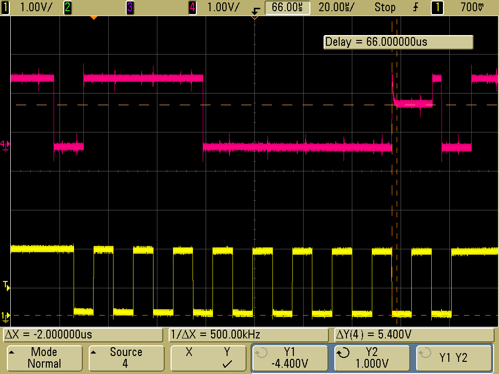
    Attached pictures are from our O-Scope, I have both a view of the full 9 clock cycles and a close in view of the ACK bit.  The pink is the SDA (sorry, I couldn’t find my good probe and the one I had was rather noisy, but it correctly shows the performance).  So first the device was powered up and then reset, then we attempted to write the register to select one of the switches.  So you can see the start condition, address and write bits are fine.  During the ACK you can see the FPGA release SDA like it should after the 8th clock cycle, and then the TCA9548 tries to pull it low, but it seems to be having a hard time, and it only gets down to 1.0V.  I guess I would suspect the resistor is too strong of a pullup, but I’ve never seen where 4.7k is too strong, that’s a pretty normal pullup for I2C.  Note we’re running very slow, something like 63kHz.

    thanks,

    JJ

  • Jonathan,

    Thank you for the waveform. As usual, a picture is worth a thousand words!


    In short, this waveform is WAY TOO CLEAN to be I2C. I have never seen a rise time this fast at 400 kHz with a RC time constant that was reasonable. Especially since the schematic shows a 4.7k resistor, I would expect to see a very rounded rise time.

    You have way too much current flowing on the bus. I'm not sure where it is coming from, either way too many pull up resistors, or your master is sending data as a push-pull setup.

    You can do the following to help confirm this:
    1) Bluewire onto the I2C bus
    2) Get a multimeter and measure the current from the I2C bus if you short it to ground. This should be rather small (0.1 to 3 mA), but i suspect that you will see something much larger.

    The reason I think this is because when the TCA9548A starts to pull down on the bus, you can see the RC time constant as it is only able to pull it down to 1V.

    Looking at the datasheet, when VCC = 1.8V, the VOL of our device is about 0.4 V at 6 mA of load current or a Rpd = 66 ohms. To achieve a 1 V drop, I estimate you'll see a current of ~15 mA (probably more, because our datasheets are a bit conservative).