Part Number: PCA9515A
I designed an I2C interface with PCA9515A show in the attached schematic.
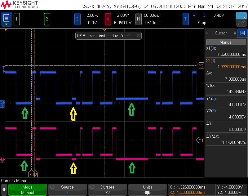
I probed Pin3 and Pin6 when there was I2C communication on the bus, and got the data show in attached picture.
My understanding is Pin 6 (output, pink line) should repeat Pin 3 (input, blue line).
But the positions pointed by yellow arrows, there is a pulse less than 1V and it's inverted at output.
The positions pointed by green arrows, the logic low is not close to the ground.
The good is that I2C can work, but confused by the measurement. Please help to explain this problem.
Thank you,
Shiwei