This thread has been locked.

If you have a related question, please click the "Ask a related question" button in the top right corner. The newly created question will be automatically linked to this question.

DS90UB928Q-Q1: Video Transmission from DS90UB929-Q1EVM (HDMI in) to DS90UB928Q-Q1 (LVDS out)

Part Number: DS90UB928Q-Q1
Other Parts Discussed in Thread: DS90UB929-Q1EVM,

Hello,

to test our self-developed board with the DS90UB928Q-Q1 we use an evaluation board DS90UB929-Q1EVM.Our board ios connected to a LVDS Display and has an EDID EEPROM on board.

The connection shall be done by HSD connectors, the final cables are not available yet, so I soldered about 15cm of twisted cables directly to the pins and connected the boards.

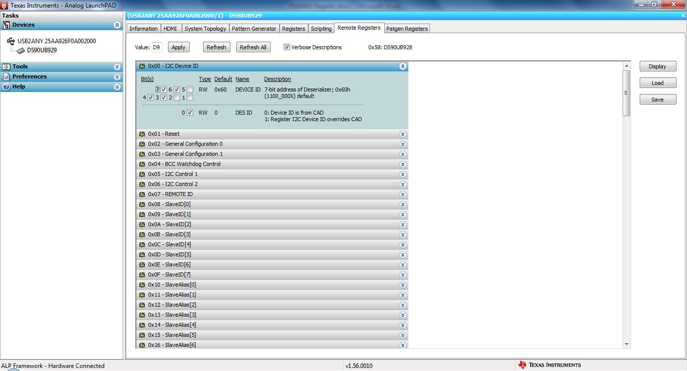
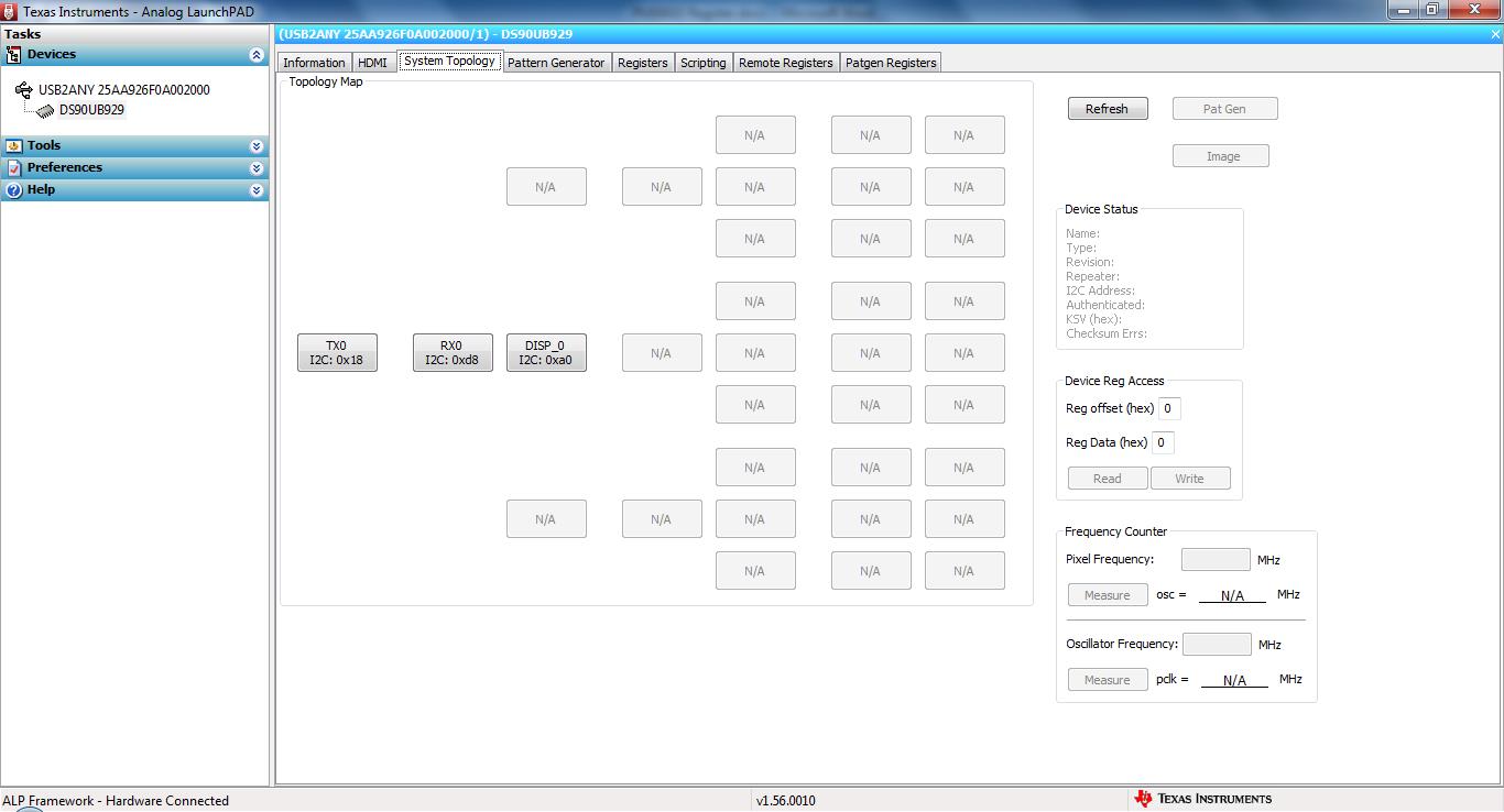
When connecting a Laptop by USB to the DS90UB929-Q1EVM and starting the "Analog Launch Pad" Software it is possible to see the System Topology (TX0, RX0 and DISP_0). With the pattern Generator the colors and patterns can be displayed on the LVDS Display.  The "Mode_1" was changed from the "1" to the "2" position so the DS90UB929-Q1EVM reads the information from the EDID EEPROM to its EDID SRAM. When I connect an HDMI cable from the Laptop to the Eval Board I can see the EDID Information from our board (name and resolution) Graphic Option of Windows. But when I connect the HDMI cable, in the System Topology only the TX0 can be seen, the others are no longer available and the HDMI data from the Laptop cannot be seen on the LVDS Display.

Could this be an issue because of the cables? There are small Stub-Lengths in the HSD Connector, could these cause the problem? Our Could You please give me another hint how to solve the problem?

Thanks.

  • Hello,

    Likely this is due to the HDMI as when running pattern generator you did not see issue on the link. When connecting the HDMI input, the 929 will use this as reference instead of internal clock.

    Basic check would be to establish lock status (LOCK pin = HIGH) and then whether you can read/write registers to the 928.

    Regards,

    Liam

  • Hello,

    Lock Pin goes High after Board is powered on, it goes Low when HDMI connector is plugged in. It is possible to read and write the (remote) registers of the 928, e.g. the I2C Device ID Register.

    System Topology shows ID 0x58 for RX0 when board is powered on. I2C Device ID: Set bit 0 to enable Device ID overwriting. Set Bit 7, Apply, Device ID "0xd8" is shown in System Topology. To check if the data is only displayed in the software or written to the register I restarted Analog Launch Pad after writing and the value of the Device ID was still the same. 

    Thank You.

    Regards

    Markus Schweizer

  • Hello,

    as an additional information: The "Lock" Signal is not always Low, there are little positive Spikes when the HDMI cable is connected.

    Regards

    Markus Schweizer

  • We received the cable (Leoni Darar 353), 1m long. Now the System Topology Map keeps all 3 elements. When we use the system without our EDID EEPROM the Windows screen is displayed, but with wrong colors and wrong solution. When we use our EDID EEPROM the display stays black.
  • Hello,
    It sounds like you have now a solid lock status (Lock = HIGH) which is required for video transmission over FPD-Link.
    Most likely the issue is related to the EDID. The default EDID in 929 would not necessarily match your display which would cause wrong image.
    You can also try loading your EDID into the internal memory of 929 to verify this values produce correct image before loading off of EEPROM.
    Liam
  • Hello,

    we solved the problem. It was a mixture of cable-issues and the format of the EDID Data.