This thread has been locked.

If you have a related question, please click the "Ask a related question" button in the top right corner. The newly created question will be automatically linked to this question.

SN65HVD233-Q1: PCAN-USB Connectivity Problem ( 3.3V - 5V CAN Interoperatibility )

Part Number: SN65HVD233-Q1
Other Parts Discussed in Thread: SN65HVD233, ADS1262

Hi,

We have a board with SN65HVD233 3.3V CAN transceivers. We monitor our CAN interfaces with PCAN-USB (CAN-to-USB) converter of Peak Systems.  

Link : http://www.peak-system.com/PCAN-USB.199.0.html?L=1

Let me define our problem. We had a Revision 1 board where we have no CAN bus problem. SN65HVD233 and PCAN-USB communicated without any problem at 250 Kbps.

Having made several capacitor-resistor additions on completely irrelevant section of the PCB, I have Revision 2 board manufactured. And now, i have the following problem :

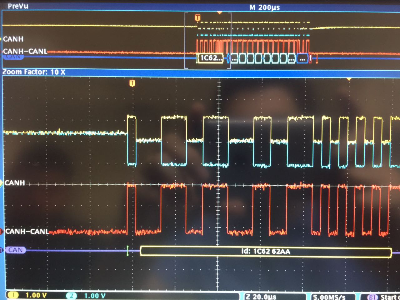
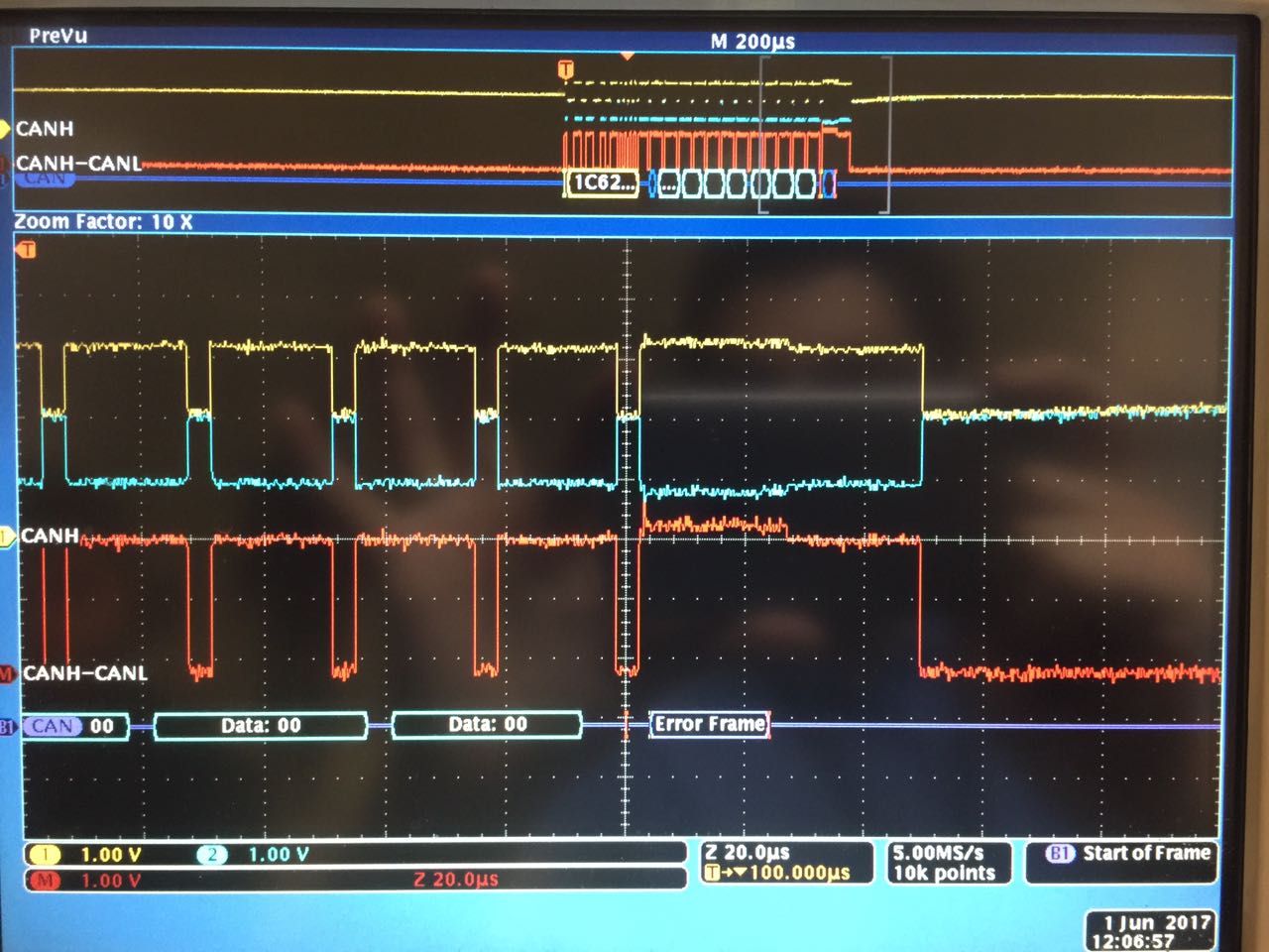
1) SN65HVD233  cannot communicate with PCAN-USB  at 250 Kbps. Receive-RX (From PCAN-USB to SN65HVD233  ) works perfectly. Transmit-TX (From SN65HVD233 to PCAN-SUB ) doesn't work at 250 Kbps. Weirdly, while i cannot transmit data 00 to PCAN-USB, PCAN-USB somehow manages to capture some of the data AA

2) When, we reduced CAN bus speed to 10 Kbps, we managed to establish a somehow stable connection. Using this 10 Kbps, we tested other functions on the board. But this connection also crumbled all the time.

3)  Other functions on my Revision 2 board, ADC, DAC, Digital IOs and EEPROM all work as intented. So, there is not a general problem on PCB.

4) I connected CAN interfaces of Revision 1 and Revision 2 boards to each other. In this scheme, my Revision 2 board send a data at 250 Kbps, Revision 1 board reads it and transmit it back after incrementing data by one. This way i made sure that SN65HVD233 Chip or my CPU on Revision 2 board is working fine.

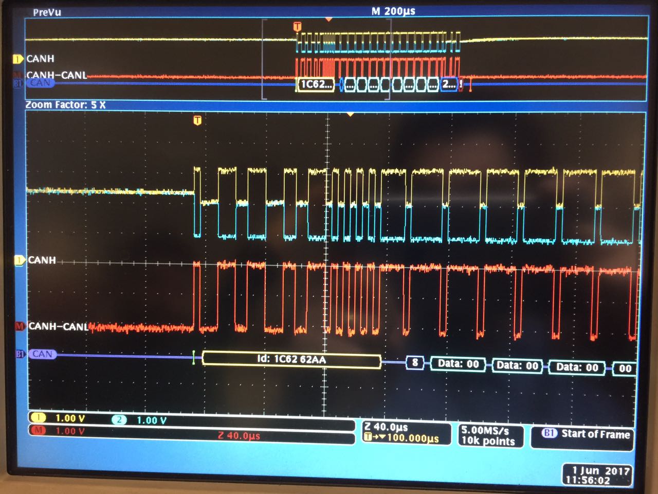
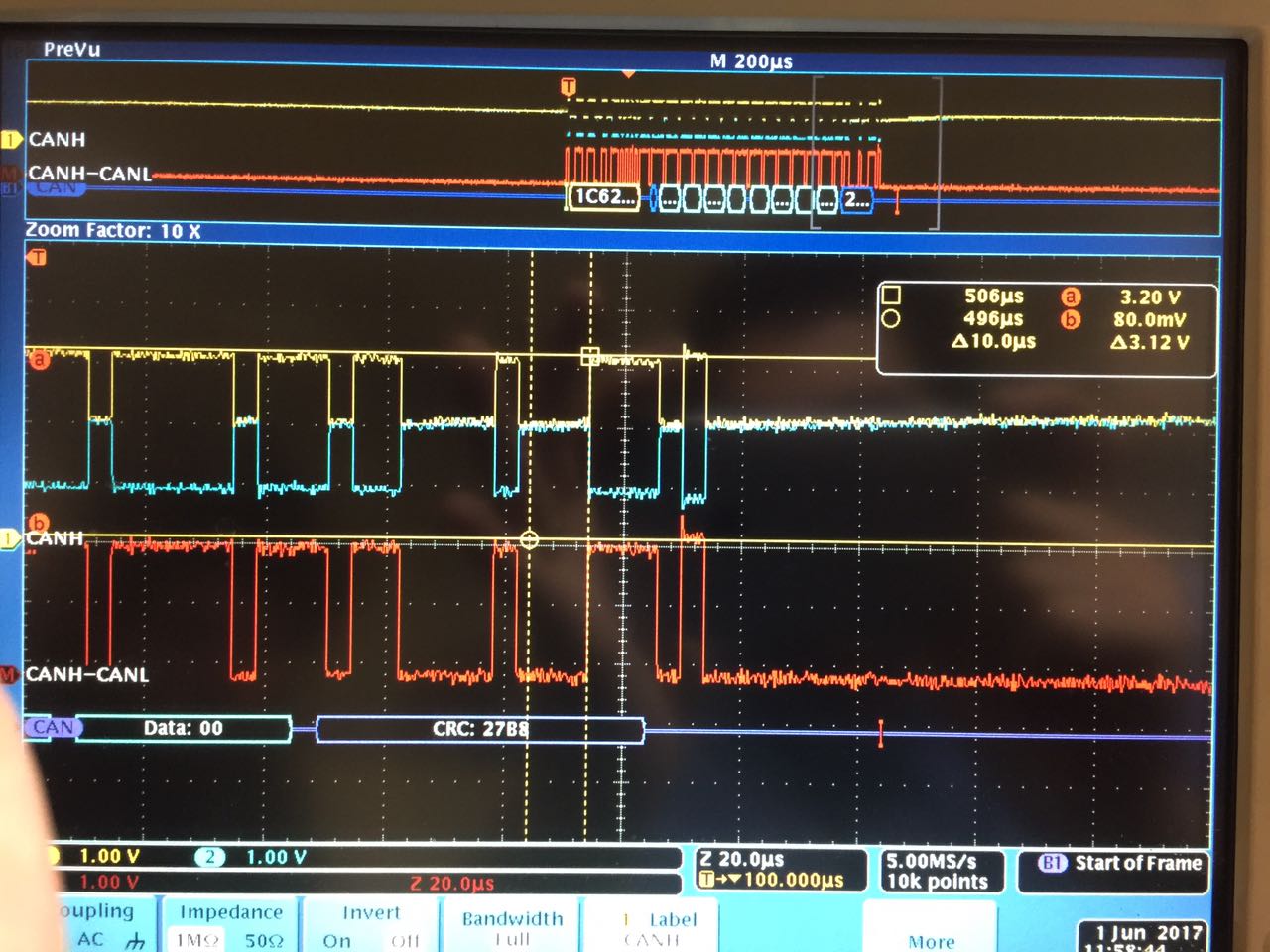
5) During the last few days, i monitored CAN outputs of Revision 2 board on Oscilloscope. What is see is that; Identifier, data and CRC are all correct. However, when i connect PCAN-USB to the board, PCAN-USB interrupts data at one point (changing everytime) and places an error frame. That's why i can't read data from PCAN-USB.

6)  Timings and signal quality is indistiguishable from Revision 1 board. However, i didn't care much attention to voltage levels as they seemed similar. I will now look into this aspect now. Before that, i wanted to consult to you :

- As i tried almost anything during the last few days, i now think problem could have something to do with 3.3V and 5V interoperability. Yes, my Revision 1 board works fine with PCAN-USB but i suspect that Revision 2 PCB manufacturing may broke down already fragile (and so far unknown) balance. One other reason that pushes me to think like this is that there is 3.3V-GND impedance difference between Revision 1 and Revision 2 boards.

- SN65HVD233 datasheet and SLLA337 (Overview of 3.3V CAN XCVRs) document states that 3.3V TI CAN transceivers are compatible with 5V CAN transceivers. But, the points i put above makes me suspect a 5V interoperability problem. ( Especially working connection between Revision 1 and Revision 2 boards). By the way, i used 3 different PCAN-USB cables, so i am sure that PCAN-USB cable is not the problem.

What are your opinions ? Do you think it may be due to different voltage systems ? Or do you have any other ideas that i am missing ?

Thanks in advance, any help is appreciated.

Regards,

Mehmet

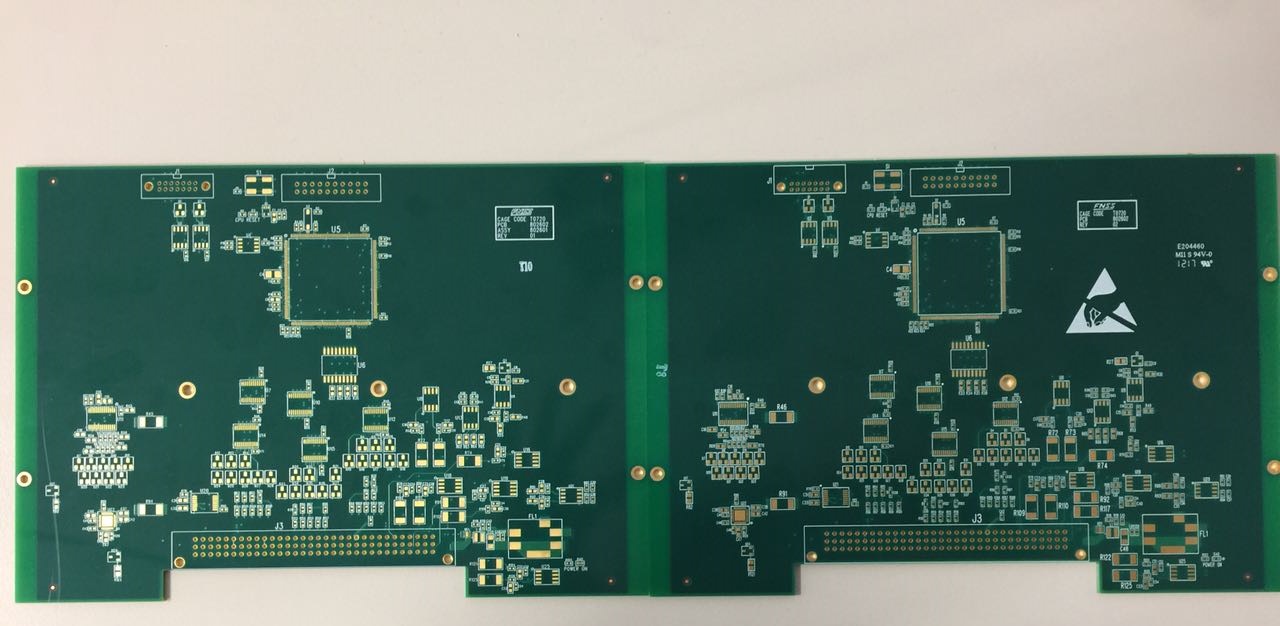
Note : In order to show you there is no layout differences between Revision 1 and Revision 2 boards, i am adding their photos. SN65HVD233 ICs are on the upper left.

  • Hi Mehmet,

    Do you think we could take a look at the CANH and CANL waveforms for a working system (Rev 1) and a failing system (Rev 2) when the issue occurs? That may help us get a better sense of what is going wrong. I don't see any issues at the schematic level.

    Are there any differences in which components are populated between the different revisions? For example, is the RS pin pulled to ground through 0 Ohms in both cases? And, is termination populated on both revisions? (Along similar lines, is all the testing being conducted with termination populated on exactly two nodes on the network?)

    What did you mean by a 3.3-V/ground impedance difference between boards? Are you just using a multimeter to measure the resistance from the 3.3-V power rail to ground when the system is unpowered? Do you see any issues on the 3.3-V supply when the boards are operating (e.g., lower DC level, higher noise, etc.)?

    Max
  • Hi Max,

    I will post detailed CANH and CANL waveforms today for both boards.

    I put photos of both revisions in the first post. There is virtually no layout difference between Revision 1 and Revision 2 boards in terms of CAN interface. In fact, only difference between Revision 1 and Revision 2 is the addition of some pull-ups and 100nF coupling capacitors in some digital IOs.

    RS pin is pulled low with 0 ohm to GND in both Revision 1 and Revision 2. I tried to raise it in Revision 2 board but this only made the situation worse ( by slowing down rise/fall times)

    I measured 3.3V-GND impedance difference with multimeter while board is powered-off. CANH-to-GND and CANL-to-GND impedance are also different. Revision 1 board had around 100k for both while Revision 2 board had around 60k.

    As for noise, i couldn't realize any difference between two boards but as i mentioned in the first post, i will take much more detailed voltage measurements today. I don't think there is general 3.3V problem though. I have both ADC and DAC on my board and my tests with them are as accurate as the Revision 1 board.

    If you need any other information other than CANH and CANL waveforms please tell me. 

    Regards,

    Mehmet

  • Hi Max,

    I may finally share more detailed information. 3V3-GND impedance in Revision 2 board is 47.4 ohm. Impedance in Revision 1 board is much higher. Both Revision 1 and Revision 2 boards are programmed to send 8-byte 00 data for every second.

    Waveforms :

     1) Revision 1 without PCAN-USB connection :

    Data is correct.

     2) Revision 1 with PCAN-USB connection :

    As you see, PCAN-USB placed ACK at the end of the frame. It has slighlty higher voltage than my 3.3V CAN bus.

    3) Revision 2 without PCAN-USB connection :


    Data is correct again.


     4) Revision 2 with PCAN-USB connection :


    Now PCAN-USB connected to Revision 2, PCAN-USB places an error frame at some point, interrupting data.

    This time i focused on voltage levels but difference are only on the order of tens of milivolts. Any ideas about what could be triggering PCAN-USB to place an error frame ?

  • Mehmet,

    Thanks for all the great info you've provided. You're looking into all the right things, but unfortunately I still don't see any reason why the Rev 2 waveforms should cause any kind of error.

    I'm fairly certain that your interpretation of the waveforms (smaller amplitude = HVD233 transmitting, larger amplitude = PCAN-USB transmitting) is correct. It may be good to confirm this by monitoring the TXD line on your PCB, though, just to make sure we aren't missing something.

    Does the error frame always show up in the same position (at the end of the frame being transmitted by your Rev 2 PCB), or does it ever show up earlier?

    Is there any chance the oscillator on your Rev 2 PCB is skewed in frequency compared to what is on Rev 1 and on PCAN-USB? If there are timing mismatches then PCAN-USB may be sampling the wrong bits, potentially oversampling the low periods as six dominant bits rather than five dominant bits followed by a recessive bit. This would cause a stuffing error to be detected.

    Along similar lines, have you tried any other data patterns? Constant lows or highs would be a worst-case condition if there are timing issues; having a data pattern like 0x55 or 0xAA repeating may yield better performance (since CAN controllers sync to the incoming data based on detection of edge transitions).

    Max
  • Hi Max,

    In my first post, i stated that " Weirdly, while i cannot transmit data 00 to PCAN-USB, PCAN-USB somehow manages to capture some of the data AA". You are right about this; PCAN-USB begin to capture AA data ( but still missing sometimes).

    This (along with somewhat stable lowered 10 Kbps connection) suggests a timing problem. But from scope values, i see very sharp 4us duration for each bits. Furthermore, dont't you think if frequency of my CPU was skewed, it would have affected some other peripheral ICs on my board as well ? For example TI ADS1262 Analog to Digital Converter IC ?

    I input my CPU with 25 MHz , 100 ppm crystal. I will look unto frequency situation by outputting that frequency from my CPU. Do you think it would be wise to use crystal on the first board with wires ?

    To check a possible power supply problem, i supplied both boards ( Rev1 and Rev2) from Rev2's power supply circuitry. Still, Rev2 works fine while Rev1 doesn't work.

    Error frame doesn't show up in the same place everytime. I send 8-bytes of 00s, and PCAN-USB places error frame after 1,2,3 or 4 bytes.

    What confused me most ( and led me to open a thread here) was successful connection between Rev1 and Rev2 boards. Yes, i am inclined to believe a "skewed frequency" or "noisy PCB" theories, but how is Rev2 board able to communicate with Rev1 board ?
  • Max,

    Thank you so much for me giving a great insight with your post. Your "skewed frequency" idea led me to inquire more about CPU frequency input.

    My colleague who is developing software of this board, realized that we don't use external 25 MHz clock but internal 16 MHz clock. This was the case with Revision 1 board too.

    When i changed CPU's clock input to 25 MHz external crystal, the problem is fixed. It is a mystery to me why Rev1 board CAN is working fine with internal clock while Rev2 board CAN is not working.

    The problem is caused by CPU not TI's SN65HVD233 Transceiver. I will be searching for why ST's processor is behaving like this.

    Thanks for your help. I was really tired of taking dozens of measurements and not seeing anything different.

    Mehmet
  • Hi Mehmet,

    Thanks for the update. I'm glad to hear the issue has been resolved! Please don't hesitate to contact us again if you have any questions or encounter any more problems.

    Best regards,
    Max