This thread has been locked.
If you have a related question, please click the "Ask a related question" button in the top right corner. The newly created question will be automatically linked to this question.
Hi team,
The customer has some questions for DS125DF1610.
Q1: He needs to cross the P pin and the N pin for the input channels and the output channels.
According to the 7.3.10 Output Driver Polarity Inversion of the datasheet, he needs to set the the pre, main and post of FIR.
How to set the pre, main and post of FIR if he crosses the P pin and the N pin for the input channels and the output channels?
What are the main(FIR_C0_SGN) value, the pre(FIR_CN1_SGN) value and the post(FIR_CP1_SGN) value? 0 or 1?
Does the FIR_CO[0-5], the FIR_CN1[0-5] and the FIR_CP1[0-5] keep the default values?
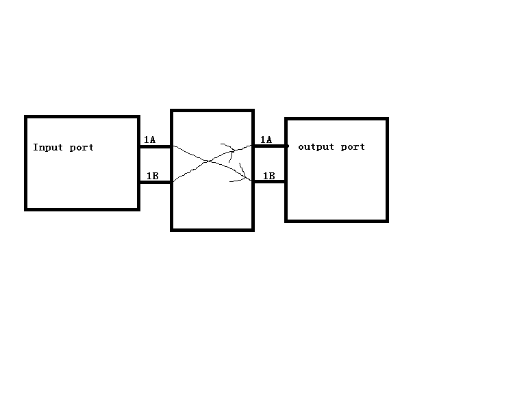
Q2: For the layout more convenient, he also needs to cross the internal logic, like input 1B, then output 1A; input 1A, then output 1B.
Please check the attachment. For this question, how to configure the registers?
Best Wishes,
Mickey Zhang
Asia Customer Support Center
Texas Instruments
Hi,
Q1 - To invert data polarity, the user should flip sign for each of the FIR taps for the channel where the output is being observed. If data received at channel 0 is being routed to channel 1 via the crosspoint, then the user should adjust the FIR settings for channel 1.
Q2- Below is an example to show the register writes necessary to configure Quad 0 such that the input of channel 0 is routed to the output of channel 1, while the input of channel 1 is routed to the outputs of channel 0.
Share Register |
Write Value |
Mask |
Comment |
0xFC |
0x01 |
0xFF |
Select channel registers of Quad 0 channel 0 |
0xFD |
0x00 |
0xFF |
|
0xFF |
0x01 |
0x01 |
|
0x9B |
0x01 |
0x03 |
Set the CDR of channel 0 to interface with the control bus for the EQ in channel 1 |
0x96 |
0x1D |
0x3F |
Enable cross point switching, enable the local buffer, enable multi point buffer. Set CDR of channel 0 to receive data from the EQ in channel 1 |
0xFC |
0x02 |
0xFF |
Select channel registers of Quad 0 channel 1. Note global registers 0xFD and 0xFF are still properly configured |
0x9B |
0x00 |
0x03 |
Set channel 1 ‘s mux to receive the EQ control bus from the EQ on channel 0 |
0x96 |
0x1C |
0x3F |
Enable cross point switching, enable the local buffer, enable multi point buffer. Configure the channel 1 mux to receive data from the EQ on channel 0 |
Note that in this example channel 1 was assigned master control over channel 0’s EQ. Since
channel 1 is the only channel connected to the EQ of channel 0, it must have master control over
the EQ.
Continuing with this example, if it was desired to switch back to normal operation where channel
0 gets its data from the EQ on channel 0, then the cross point enable bit can simply be disabled.
Users should avoid turning off both the local buffer and multi-drive buffer when using the cross
point. When configuring for a point to point switch, users should have both the local and multidrive
buffer enabled.
Hi Rodrigo,
Thanks for your help. For the Q2, I have understood.
But for the Q1, I still cannot understand. The customer's purpose is to cross the N pin and the P pin for the input channel
or the output channel. For example,TX_1A_P is A1 pin and TX_1A_N is B1 pin. Now the customer needs to
set A1 pin is TX_1A_N and B1 pin is TX_1A_P.
According to the 7.3.10 Output Driver Polarity Inversion of the datasheet, he needs to set the the pre, main and post of FIR.
How to set the pre, main and post of FIR ? Would you explain more about this?
How to configure the main(FIR_C0_SGN) value, the pre(FIR_CN1_SGN) value and the post(FIR_CP1_SGN) value? 0 or 1?
How to configure the FIR_CO[0-5], the FIR_CN1[0-5] and the FIR_CP1[0-5] values?
Hi Mickey. We have a retimer programming guide document that captures all of these details. Do provide me your email address and I can share the programming guide with you.
Rodrigo Natal
HSSC Applications Engineer