This thread has been locked.

If you have a related question, please click the "Ask a related question" button in the top right corner. The newly created question will be automatically linked to this question.

TPS25740A: TPS25740A questions

Part Number: TPS25740A
Other Parts Discussed in Thread: TPS25740B, TPS25741A

Team, 

My customer is working on a project using our TPS25740A, and has a few questions:

I’m testing with the TPS25740A, and I think I’m seeing a violation according to the datasheet. It appears that the TPS25740A is registering a SUVP (Slow Under-Voltage Protection) fault after the IC has switched in the additional SMPS feedback resistors. The datasheet says that during voltage transitions, the SUVP is disabled.

 In the attached photo:

  • Blue = SMPS output
  • Yellow = VBUS switched output controlled by the TPS25740A
  • Green = CTRL1 or CTRL2 … pulled to GND is when the voltage is supposed to start transitioning


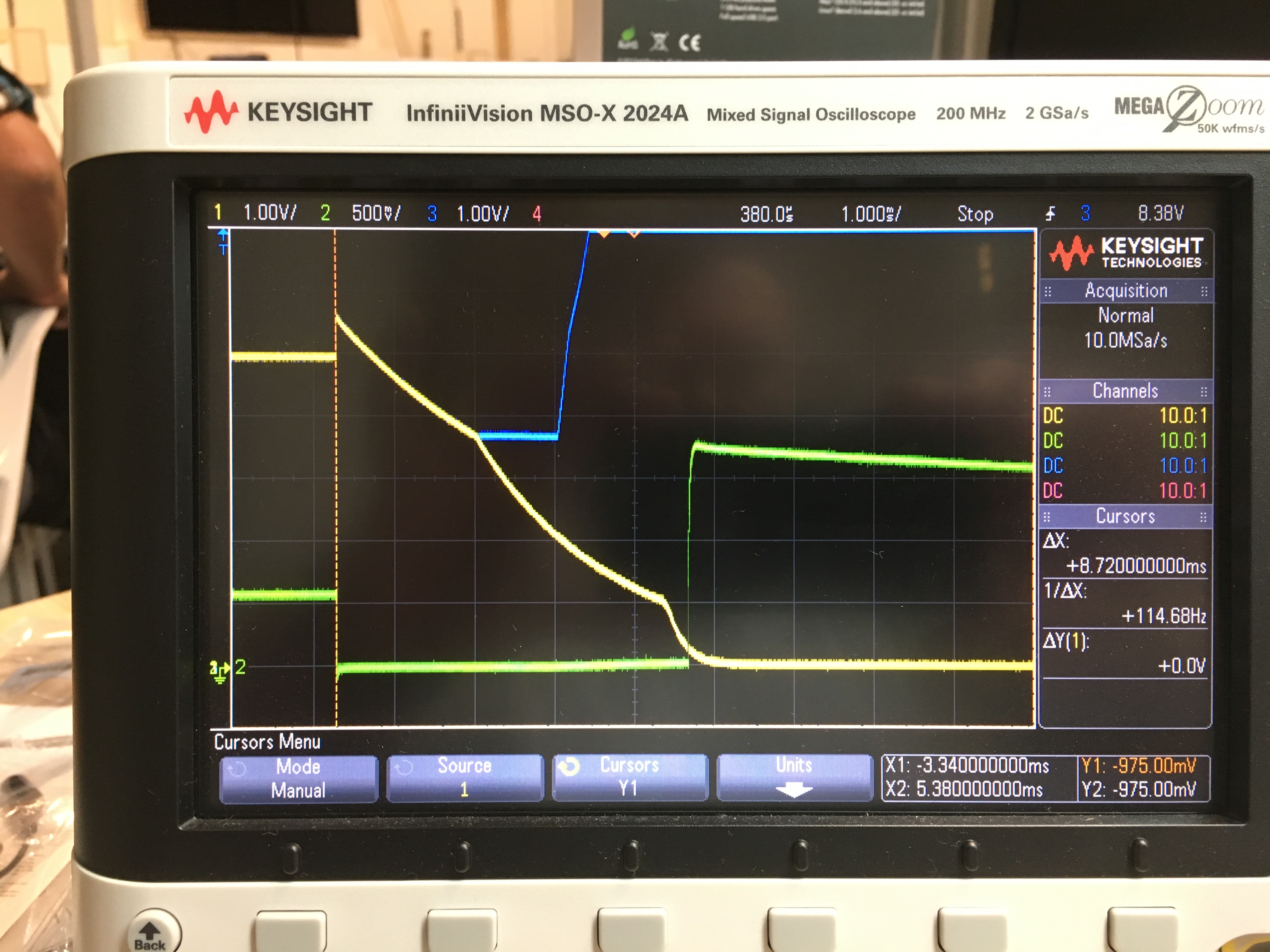
I also have an issue in the SMPS that it gets a spike at the beginning of the transition, stops regulating, then the VBUS voltage droops. You can see where it crosses the SUVP limit and VBUS is turned OFF.

 Another aspect to this issue is that this happens when I load the PD Device with a 0.1A resistive load. If I remove that load, everything transitions correctly. There is still a dip in the SMPS output, but it is much smaller and doesn’t appear to activate the SUVP fault.

 I would love to find out that this is an error in the TPS25740A die that was corrected in the TPS25740B! I need to apply some “fixes” to my board, then I can repeat this testing on the “B” version.


Thanks

Viktorija

  • Hi Viktorija,

    Could you post the schematic? I'm wondering if it may have something to do with the DC/DC.

    Regards,
    Donovan
  • OP, here ... sorry, schematic is under NDA.

    I agree ... there is "something" going on with the DC/DC converter. It looks to me that a change in the FB resistors setting the output voltage causes the chip to reset as though it were starting up for the first time. When the supply starts back up (blue line is increasing to +15V), the ramp-rate is consistent with soft-start.

    However, based on the TPS25740A datasheet, it looks like the SUVP is activating, and while the SMPS output voltage does go to +15V after a short delay, the TPS25740A may have already registered a fault and gone into "reset" mode. After the SMPS takes the output to +15V, the TPS25740A switches out additional FB resistors to take the SMPS output back to +5V. Using a PD analyzer you can see the handshaking starts all over with the same result.

    Please refer to the datasheet Figure 1. It details when the "soft" over/under voltage protection applies relative to voltage transitions. The down-slope following the addition of the FB resistors, the SMPS stops switching, and the VBUS voltage decays. The "corner" in that decay is consistent with SUVP limit.
  • Here's something more ...

    I see VPWR has a Under-Voltage Lock-Out [V(VPWR_FTH)] at around 3.7V. If I'm "browning out" the TPS25740A that could explain why I don't see a "Hard_Reset" message when reviewing the PD CC logs.
  • Hi rojo-mojo,

    I think you are correct that the device is in Under-Voltage Lock-Out. The timing for the SUVP isn't anywhere close to when it would occur and it looks like the DC/DC is browning out once the voltage is increased. Does this happen anytime the voltage is changed from 5 to 9 or 15 volts?  Let me keep looking into it.

    Regards,
    Donovan

  • Yes, this occurs when transitioning from +5V to +9V and +5V to +15V. If my device load is under 20mA, the transition works fine. If I have any load higher than 20mA, it goes into this mode.

    Also a mystery here ... why does switching in the FB resistors cause a spike in the output? There is a corresponding "spike" increase in the SMPS output and FB input when the TPS25741A pulls the FB resistor to GND. Also, upon closer inspection, I see that the SMPS changes from Pulse-Skip-Mode to Continuous mode.

    I'm waiting on some answers from the SMPS vendor (sorry, not TI) to tell me if spikes on the FB input causes it to reset.
  • Hi rojo-mojo,

    We have experienced a similar problem with the DC/DC being in CCM. Switching the DC/DC to DCM fixed this issue.  I'm not sure about the DC/DC in this design but the feedback network seems to be the issue. 

    I'm unsure about the spike but maybe it does have to do with the DC/DC being in Pulse-Skip-Mode and switching to CCM.

    Regards,
    Donovan

  • Current thinking from SMPS vendor is:

    1. Loop bandwidth is not fast enough to handle a step response change in the FB node due to switching in additional resistors.

    2. It's possible I'm hitting over-current limits in the SMPS. This causes a "reset" and "soft-start". Each of those last 2msec ... somewhat consistent with the plot above.
  • I have another +5V rail in the design. I diode OR'ed that with my VADJ into the TPS25740A VPWR pin in order to hold is up when VADJ droops below +5V. This worked great, but the TPS25740A still resets.

    Does the VBUS Threshold (Falling Voltage) [V(VBUS_FTH)] also cause a reset?

    While I strapped VPWR, VBUS will still droop.
  • Hi rojo-mojo,

    Yes. If Vvbus_fth falls below 3.7V then it is considered an OCP event and sends a hard reset signal is sent.

    Regards,
    Donovan
  • I applied the circuit recommended in the datasheet (TPS25740A Figure 41. Slew-Rate Control Example No. 1). It works great!

    The loop stability of the SMPS cannot withstand a step in the FB node without causing a shutdown event. This in turn drooped VPWR and VBUS into the TPS25740A. Slowing down the "speed" with which the additional resistors are added to the FB node fixes the issue.

    Reworking the board with discrete components was difficult. I'd recommend anyone designing a new circuit put this in with bypass zero-ohm jumpers as a backup until you know how the interaction between the PD Controller and the SMPS will work.

    The other advantage to adding this circuit is it allows the FB resistors/FET ground to be connected to the SMPS ground plane. In our design we tie our SMPS ground plane to the inner plane a one location to control the SMPS currents. The TPS25740A is terminated to the inner ground plane. This creates some impedance between the fixed FB resistor for +5V operation and the two that the TPS25740A switches in.
  • Also, does TI have a buck SMPS regulator that can be used for this application?
    * Vin = +20V to +28V
    * Vout = +5V to +20V
    * Iout = 3A continuous
    * Internal Switch
    * 1MHz+ Switching Frequency
    * Enable = Active HI
    * Internal Current/Thermal Protection
    * Cost-effective/low-part count
  • Hi Rojo,

    For advice on Buck regulators, please post a new thread in the Buck DC/DC forum. You will get the best advice from our experts in that forum. I'm closing this thread for now, but feel free to re-open if problem still persists or you can also start a new thread in this forum. Thank you for choosing TI parts for your project :-)