This thread has been locked.

If you have a related question, please click the "Ask a related question" button in the top right corner. The newly created question will be automatically linked to this question.

TPS2543: About layout pattern of D+ and D- line

Guru 21045 points
Part Number: TPS2543
Other Parts Discussed in Thread: TPS2549

Hi Team,


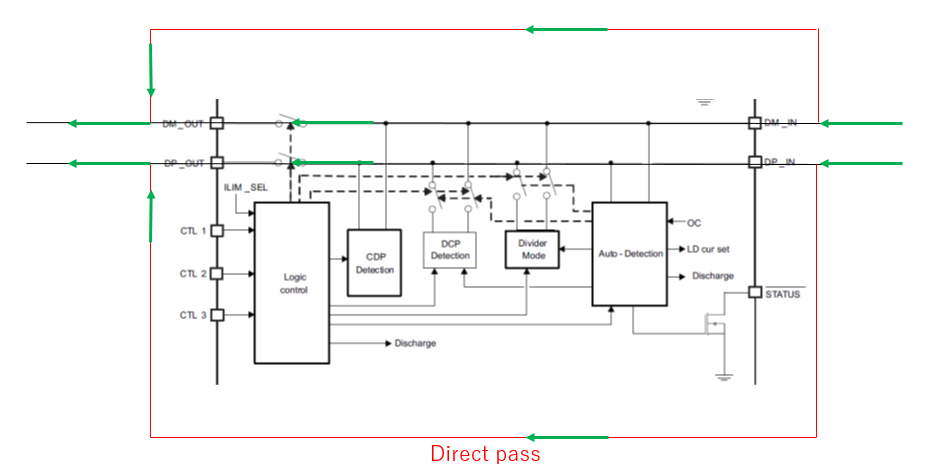
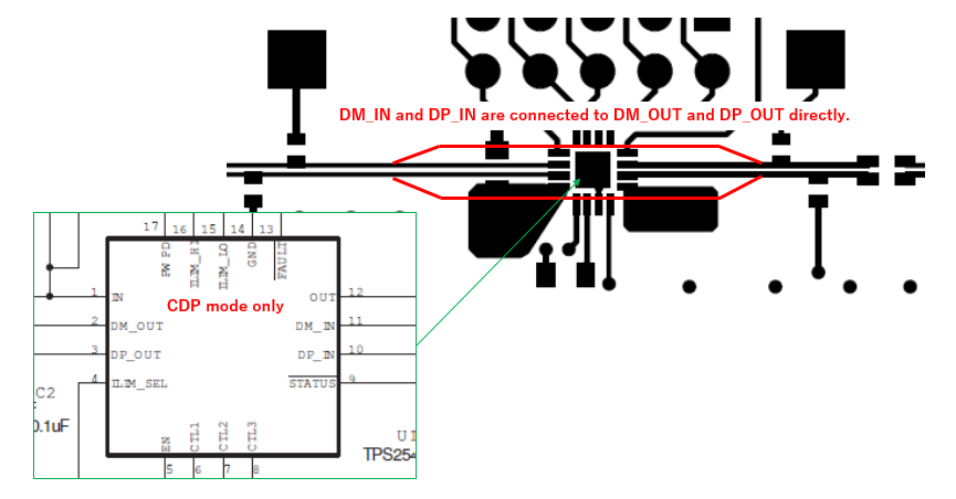
Our customer would like to use TPS2543 at the following layout pattern(please refer to the red line).

Because, they have to decrease the resistance component on the D+ and D- line to improve quality of "D+ and D- signal".

Could you please let us know if you have any concern?


[Layout pattern Image]


Regards,

Kanemaru

  • Hi Kanemaru,

    They plan on completely bypassing the TPS2543?  So they only need the current limiting capabilities of the TPS2543?  If 73 mOhms is to much they may be interested in the TPS2549 which has an Rdson of 47 mOhms.  It is ok to bypass the TPS2543 D+ D- lines if it's CDP detection capabilities are taken care of in the host controller.

    Thanks,

    Donovan  

  • Hi Donovan-san,


    No, they would like to use the internal CDP detection of TPS2543.

    Can " the internal CDP detection " not function at this layout?


    Regards,

    Kanemaru

  • Hi Kanemaru,

    No it can not. The D+ and D- lines need to pass through the TPS2543 so it can perform the proper CDP detection using the D+ and D- lines. If the Rdson is too high, I'd recommend looking at the TPS2549.

    Thanks,
    Donovan
  • Hi Donovan-san,


    Thank you for your comment.

    They would like to decrease the resistance component on the D+ and D- line so it is not "Rdson".

    According to the datasheet, “While in CDP mode, the data switches are ON even while CDP handshaking is occurring”.

    Therefore, I guess that the internal CDP detection can detect “D+ and D- line” even if DM_IN and DP_IN are connected to DM_OUT and DP_OUT directly.

    Is this correct operation?


    Regards,

    Kanemaru

  • Hi Kanemaru,

    Yes sorry for the confusion; Rdson is only for Vbus.  CDP detection requires the D+ and D- be connected internally through the device.  If it is done like the layout in the question, the D+ and D- bypass the TPS2543 and therefore bypass the internal CDP detection.

    The CDP detection is performed internally using the DM_IN and DP_IN lines which pass through to the DM_OUT and DP_OUT.

    Regards,

    Donovan 

  • Hi Donovan-san,


    Thank you for your response.

    The following figure is my image.

    D+ and D- line goes along two courses so the internal CDP detection can detect D+ and D- line.

    Therefore, I guess that TPS2543 can detect CDP mode.

    Could you please let us know if you have any concern?


    Regards,

    Kanemaru

  • Hi Kanemaru,

    Having the USB2.0 lines split into two parallel paths is bad practice and would cause signal integrity problems.

    Regards,
    Donovan
  • Hi Donovan-san,


    Thank you for the information.

    I understand that "signal integrity problems" is caused by this layout.

    Therefore, TPS2543 can’t detect CDP mode.

    Is my understanding correct?


    Regards,

    Kanemaru

  • Hi Kanemaru,

    It may be able to do CDP detection but we can not guarantee this because the device is not meant to be implemented as suggested. There should be one path through the TPS2543.

    Thanks,
    Donovan
  • Hi Donovan-san,

    Thank you for the information.

    I understand. Thank you very much.

    Regards,

    Kanemaru