This thread has been locked.

If you have a related question, please click the "Ask a related question" button in the top right corner. The newly created question will be automatically linked to this question.

TCAN337G: TCAN337 failures: best practice for ESD protection?

Part Number: TCAN337G
Other Parts Discussed in Thread: TCAN337

We have been running a system with several remote modules connected with CAN bus.

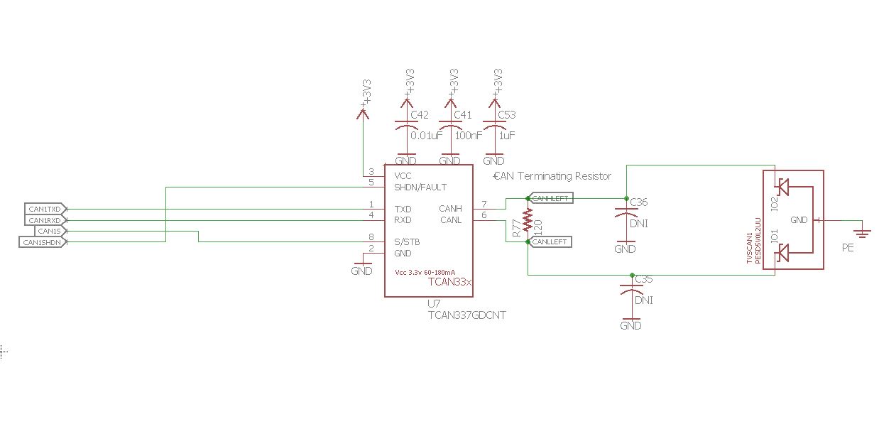
All nodes are using TCAN337 transceivers. 

All nodes are protected with PESD5V0L2UU,115 TVS diodes  tied to chassis (labeled PE in schematic below).

Symptoms: Communication on the bus will stop. After shutting the system down we will measure the impedance from CANH to CANL to be very low (less than 1 ohm). The impedance across the TVS diode will also be very low (less than 1 ohm).

The system will work fine after replacing the Transceiver and TVS diode.

This suggests that the bus was exposed to an impulse large enough to destroy the CAN transceiver and the TVS diode.

The rate of these failures has substantially reduced since adding the TVS diodes, however we still experience failures from time to time.

1) Is the PESD5V0L2UU,115 TVS diode appropriate for this application? 

2) What is the best practice for protecting the bus, should we connect the TVS diode to the Chassis (PE) or to the local ground plane?

3) Do you have any additional suggestions for improving the robustness of this system?

Thanks


  • Hi Michael,

    Have you ever tried replacing only the transceiver or only the TVS? If only one of them is breaking it might help give us some more clues as to what the weak link is here.

    Also, is there any chance the system is exposed to any DC overvoltages like a short-circuit from the CAN lines to a power rail? TVS diodes are good at clamping transients, but can be damaged by longer-term exposure to voltages beyond the working voltage range. I mention this because the working voltage range of PESD5V0L2UU is fairly narrow (0 V to 5 V). Beyond that I don't see a general issue in using this component with TCAN33x.

    I typically recommend connecting the TVS diodes to an earth ground port (like chassis PE) rather than to local grounds. This should stop transient currents from circulating on the local ground, potentially coupling noise onto the PCB and affecting other circuits like power regulators.

    The downside of this approach, though, is that differences in potential between the PE and GND nets could cause the TVS to conduct. (For example, if the PE potential is positive with respect to GND, it would be possible for the TVS to become forward biased and expose the transceiver to potentials that are "high" with respect to its local ground.) Is it possible this system has encountered any scenarios that present a difference in potential betweeo PE and GND?

    One common approach that may provide some benefit in this case would be a bleeder (large-valued) resistor and (small-valued) parallel capacitor from GND to PE. That would help prevent any long term charge accumulation between the two nets that could discharge via the TVS path. It wouldn't help for "DC" issues like short-circuits, though, since the resistance value would need to be high.

    Max
  • Thanks for the quick response Max,
    1) To clarify: I typically remove the TVS first and then recheck the CAN transceiver to see if it survived. I am able to confirm component failure by measuring the impedance of the part after it has been taken off the board.
    -Sometimes the CAN transceiver fails in isolation
    -However if the TVS has failed the CAN transceiver is always dead

    2) It is entirely possible that we are experiencing an issue with a potential on the PE relative to GND as you described. I will consider that more (can you think of any tests to detect that issue?).

    3) In theory our system is designed so that the CAN bus is more vulnerable to ESD hits when cables are disconnected. In this case, would connecting the TVS to GND (as opposed to PE) be a better choice as it might offer isolation from potential on PE relative to GND?

    4) Do you have any app notes describing use of bleeders as you described?

    Thanks for your support,
    -MM
  • Hi Michael,

    Thanks for the clarifications. Detecting a difference between PE and GND is a little tricky, since such differences sometimes only arise when the GND rail is allowed to truly "float" and thus connecting measurement equipment may skew the measurement itself somewhat. You may be able to observe something meaningful by using a high-impedance oscilloscope probe on each line, though.

    Thinking about this application a little more, it does seem like there would be benefit in connecting the TVS diodes to the local ground. Since the working voltage range of the TVS is relatively narrow, having it share a common reference with the transceiver would help the system to better tolerate minor GND/PE offsets without causing the TVS to conduct or shift its clamping voltage outside the absolute maximum range of the CAN port.

    Given that, the best solution in my mind would be to reference the TVS to the GND net but to provide a path for transients to easily flow to the PE port. Placing a high-voltage capacitor (say, 1 nF) from GND to PE could accomplish that - you would end up with DC isolation but a low-impedance path for higher-frequency transients. A resistance in the range of 1 MOhm - 10 MOhm could be placed in parallel to this capacitance in order to prevent charge accumulation. (This would result in some small leakage between GND and PE, so you would of course need to make sure that this does not violate any safety requirements for your system.) This is what I meant by a "bleeder" before - i.e., just something to provide a controlled discharge path.

    I've seen systems working without this RC network as well, but in that case the path taken by the transient currents is not so well-defined. The current would be entering a node that is basically floating, and so return currents would either find their own least-impedance path (potentially interfering with other components) or charge could accumulate on the ground net.

    I know this can be a bit confusing and it can be difficult to find good reference material, so please just let me know what further questions you have and I will do my best to help.

    Best regards,
    Max