This thread has been locked.

If you have a related question, please click the "Ask a related question" button in the top right corner. The newly created question will be automatically linked to this question.

SN65HVD3083E: How to reduce the influence of noise

Part Number: SN65HVD3083E

Hi,

I am doing a noise test on a device using SN65HVD3083E device.
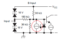
I attach a circuit diagram.
Since there is only one communication partner, it performs one-to-one communication.

For noise, noise superimposed from the AC 100 V power supply line, noise radiated from the air around the device.
It is the result that data loss often occurs due to the influence of noise.

I added 10kohm to the red circle in the circuit diagram.
In this case, the influence of noise is reduced.
It is probably because the impedance on the line decreases and resistance to noise increases.
Although I would like to implement this countermeasure, the SN65HVD3083E has a fail-safe function, which may affect the fail-safe function.

I want to ask you a question.
When adding pull-up and pull-down without affecting the fail-safe function, what resistance ohm can be added?

Best Regards,

  • Hi Kaji,

    thanks for reaching and this interesting question.

    The external pull-up and pull-down actually do the same job as the internal fail-safe function so its not affecting this in a negative way.

    Kaji@PAN said:
    It is probably because the impedance on the line decreases and resistance to noise increases.

    Yes due to the fact that you increase the current into the bus via the resistors the noise influence will be reduced. Pleas take a look at this application note it will describe how to design the fail safe resistors.

    /cfs-file/__key/communityserver-discussions-components-files/138/0537.7282.slyt324.pdf

    Maybe it is mentionable to point out that such a resistor network is constantly burning current so your total numbers of nodes (ULs) decreases.

    Let me know if this is helping you out, don't hesitate to ask further questions.

    Kind regards 

    DIerk

  • Thank you for your reply.
    As additional information, another 100Ω terminating resistor is connected to other devices.

    I had you answer that external pulling up and pulling down had no effect on device fail-safe.
    Does this mean that there is no effect even if the device failsafe works?
    Or since there is a pull-up pull-down, does device fail-safe not work so does it mean there is no influence?
    As you can see in the datasheet, the red circle seems to work.

    I think that the fail-safe function of the device does not work if it is configured as follows, is it suitable?
    The following is an illustration of the application report (slla036d).

    Best Regards,

  • Hi Kaji,

    the current source red circle in the diagram is used to mimic the leakage circuit that generates the receiver fail-safe threshold. The internal fail safe is offering fail safe for open-line cases. But you can not use this feature when you are simultaneously implement 100 Ohm for line-termination.

    The internal resistors are in the 100 KOhm range in order to keep the current consumption need for the internal fail safe - which is represented by the current source - low.

    This is not working if you use the 100 Ohm line-termination (necessary for high signal rates):

    Please take a look at Page 10 here: /cfs-file/__key/communityserver-discussions-components-files/138/1781.slla036d.pdf

    So if you are not using a lot of ULs on the bus the R1 = 2500, R3 = 110, R2 = 120 design gives you the best bus performance and noise reduction.

    Let me know if I answers your question adequate.

    Kind regards 

    Dierk

  • Thank you for your reply.
    I tried the proposed constants and it was confirmed that the noise immunity improved.
    I would like to add this external fail-safe circuit.
    However, I have a question.
    How many unit loads is the load of this fail-safe circuit?

    Best Regards,

  • Hi Kaji,

    good to hear that you found a solution benefiting your demands.This particular design represents 5.6 ULs.

    Kind regards 

    Dierk