This thread has been locked.

If you have a related question, please click the "Ask a related question" button in the top right corner. The newly created question will be automatically linked to this question.

TPS25740B: Reseting to 5V

Part Number: TPS25740B
Other Parts Discussed in Thread: LM5175, TPS25740

Hi!

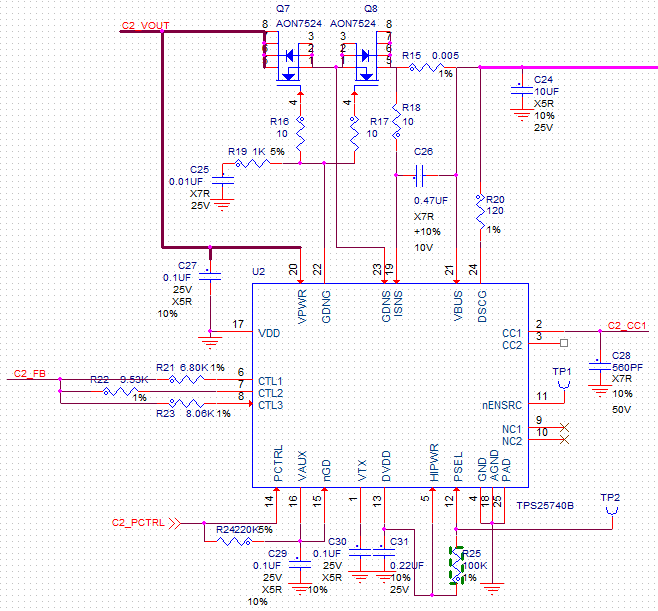
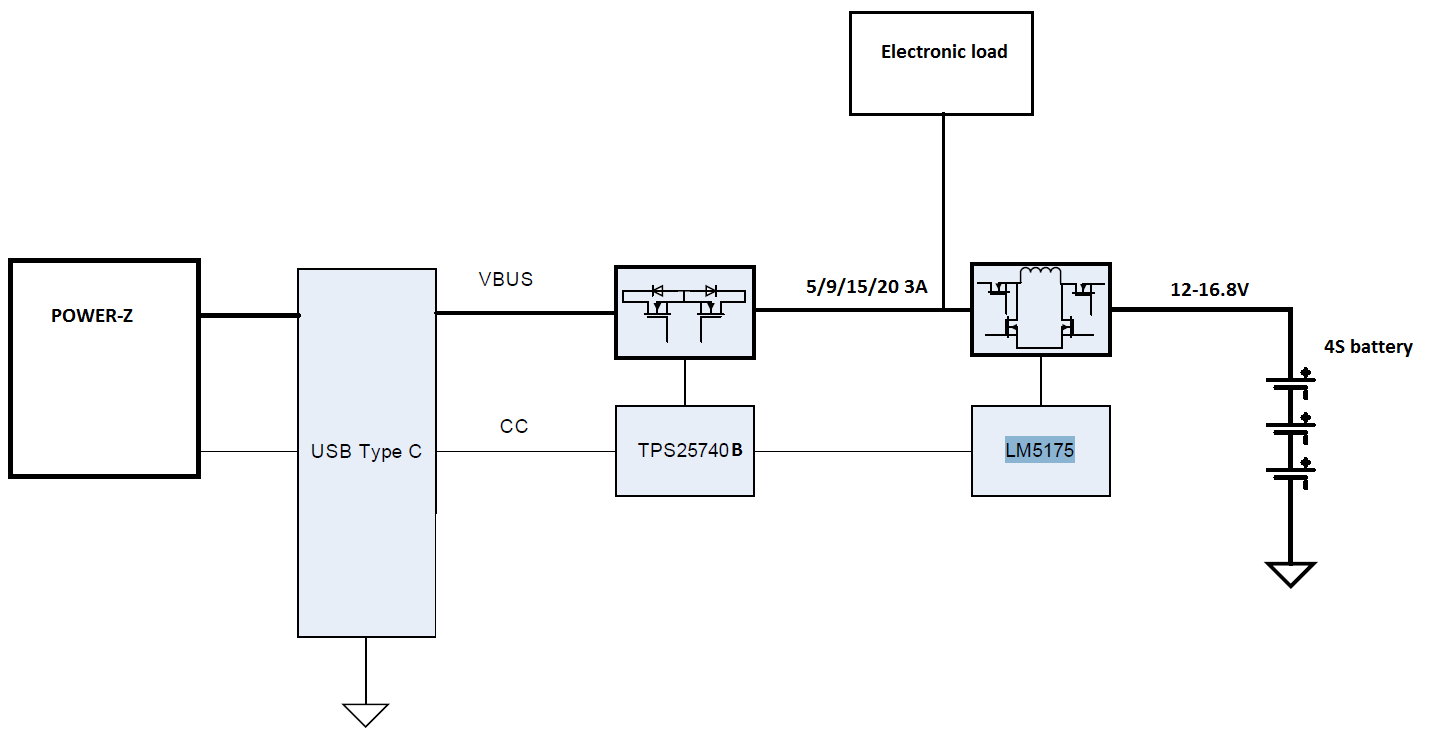
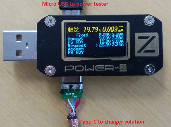
I have built PCB based on TPS25740B-741 Evaluation Module.

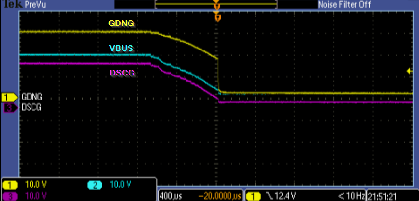
Problem I am facing is that if I apply load on Type-C port TPS25740B is disconnecting output and falling back to 5V. Then more voltage then less current is necessary to cause this. 15V need 2.6A and 20V need 0.7A

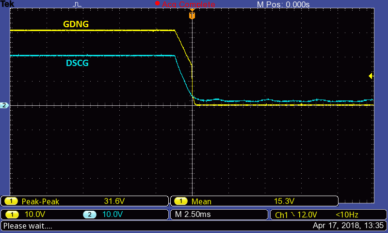
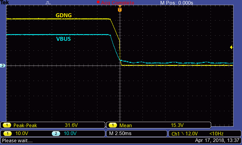
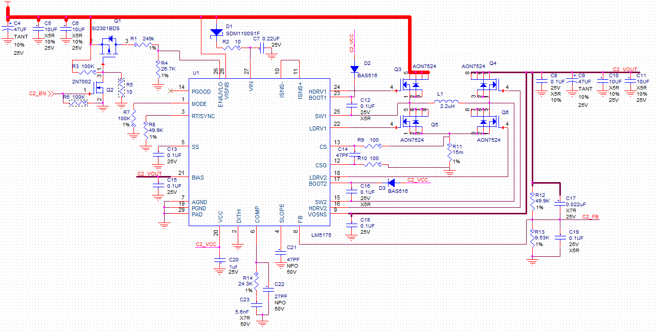
Disconnection is caused by nGD falling edge. But nGD is connected to VAUX and I don't understand why VAUX is going low for 15ms at some point.

There is no voltage drop, I have disabled current measurement by shorting ISNS to VBUS there is no overvoltage happening.

I am even connecting load to LM5175 output directly.

Does someone have ideas?

  • Hello Kristaps,

    1. Thank you for posting your question here on E2E. When you say are applying a load, are you connecting a device to charge? Or just a cable? What type of device are you plugging in and what cable are you using?

    If you aren't connecting a device, what is the load and how are you connecting it?

    2. Also would you be able to send me scope shots of the issue? I'm mainly interested to see VBUS, the output current, GDNG, and DSCG.

    3. Can you post your schematic here? Or just a picture of how you have the TPS25740B configured?

    Regards,
    Adam
  • Hello Adam,

    Thanks for quick reply.

    1. Initially I was applying resistor load on VBUS and switched voltages with Power-Z USB tester connected using type-c cable cut in half and soldered to PCB (Current sensing was disabled ). Then I started to use electronic load that is connected not through TPS25740B FET's and sense resistor, but directly to LM5175 output. Result's were identical.

    2. I had simple oscilloscope available so i have 2 scope shots  from 2 ch. Didn't had possibility to capture current, but that's not sensed by TPS25740B.

    3. Attached part of schematics.

    Kristaps

  • Hi Kristaps,

    I am confused on your test setup. Why are you breaking up a cable and putting on a load from there in addition to using the power-z USB tester. After reading through the users manual, it seems like you can adjust the load within the tester and there is no need to break out a cable. Would you be able to send me a picture of your test set up?

    Also, are you connecting to the Type-C port on the USB tester, or are you using a cable to go from Type-C to Type-A? If so, that will cause issues with your tests and will cause the TPS25740 to go from Type-C PD to BC1.2. You will need to connect from Type C to Type C

    Finally, I noticed an issue within the schematic that you sent me. You do not have CC2 (pin 3) connected to anything which can cause issues. Can you also send me the schematic capture for you configuration of the LM5175.

  • Hello Adam,

    Sorry if I mist something in explanation.

    I am making Type-C plug solution as seen in TPS25740B datasheet. Therefore I just took a half of Type-C to Type-C cable and soldered it to PCB (GND,VBUS,CC1) for tests. That is also why I use only CC1:

    Load can't be regulated on USB tester, just switched PD voltages, I initially used resistor loads that are connected through USB tester so current was going through TPS25740B controlled FET's and current sense resistors.

    Then after noticing strange behaviour I shorted C26 to disable current limiting on TPS25740B side and that didn't help.

    Then I completely eliminated current flow through TPS25740B circuit part and connected external load directly to LM5175 output and TPS25740B part now is just doing USB PD voltage switching and not influenced by current flowing through FET's and sense resistor.

    Here is block diagram:

    Tester connection (sorry, can't whow PCB):

    LM5175 part:

  • Hello Kristaps,

    I did some tests on my own, and the issue you are seeing is related to an over current event. I tested using the TPS25740BEVM, having it connected to a Type-C PD sink board, which was then connected to an electronic load controlling the amount of current that was forced throughout the system. I slowly increased the electronic load current value until the overcurrent protection features kicked in (~3.8A) and shut down the system. Below is a screenshot of the results once that current threshold was exceeded. It is almost identical to the screenshots that you sent earlier.

    I know that you shorted the capacitor connected to the ISNS pin which should completely nullify the sense resistor, R15. However, I would remove this resistor as well just to make sure.

    Also, try increasing the resistance that you connect to the load. Increasing this resistance will decrease the amount of current that is forced through the system, and once the current amount is below the 3.8A threshold, the system should be fine.

    Let me know if this fixes your problem. If it does, please click on This resolved my issue.

  • Hello Adam,

    Sorry for late reply I switched to different urgent jobs and couldn't check this solution.
    Removing R15 would make larger voltage drop on ISNS and VBUS if load applied on VBUS. Maybe you men't shorting R15 to 0 Ohm?
    Please also note that I was testing with load connected not to VBUS but to C2_VOUT which not only eliminates current sensing on ISNS but completely eliminates current flow through R15.

    I am thinking that there is some design fails of LM5175 part. (I used Webbench) Possibly ripple or something else. Will check later when I get to this project.

    Thanks,
    Kristaps
  • Kristaps,

    Yes, I ment shorting R15 to 0 ohm and not to remove it completely. Sorry for the confusion there.

    And if you truly are measuring from C2_VOUT then there is something going on with the LM5175 as the TPS25740B only has control over the fets in between C2_VOUT and VBUS. If the rail is shutting off before these fets, then your right it must have something to do with the LM5175. What I would recommend doing is closing this thread, and posting a new question but have the LM5175 be the part within the title. It will then be assigned to the team who are the experts on that specific part.

    In addition to that, I would also try to continue to trace back the problem to see if you can find the source. Measure the voltage coming into the system (voltage at C4), to see if there is any ripple from the source that is effecting the part. Also, you can try to add an external power supply to the system to see if it remains stable. How you can do that is to start your test as you have done before, but once the PD negotiation is complete, and VBUS goes to 20V, connect an external power supply to C2_VOUT and see if the voltage drop still occurs.