Other Parts Discussed in Thread: TPS61175, SN6501, PCA9544A, ADS1115-Q1, ADS124S08, TLV61220, SN6505D, SN6505A
Hello all,
I've designed and built my first isolated power stage as part of a 3V3, 5V and 5VA supply, for an instrumentation front-end. Please refer to this TI datasheet for the inspiration for the design, section 9.2 'Typical Application'. The output voltage wildly differs from the input, given that I'm using a 1:1.33 winding transformer I would expect in the region of 5V peak measuring after the MBR0520L diodes in the diagram (shown below):
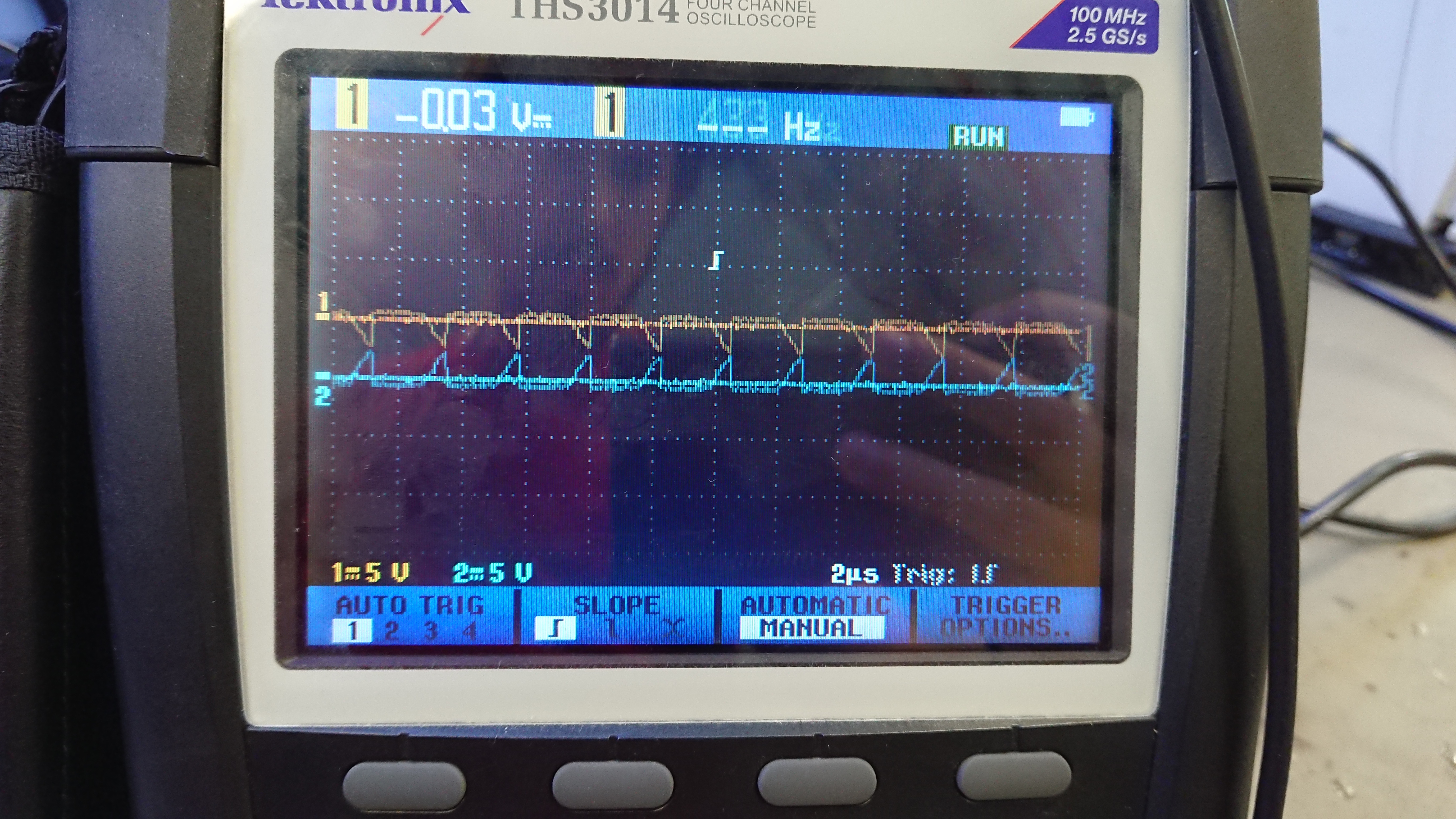
Instead the SN6505B driver puts this waveform in:

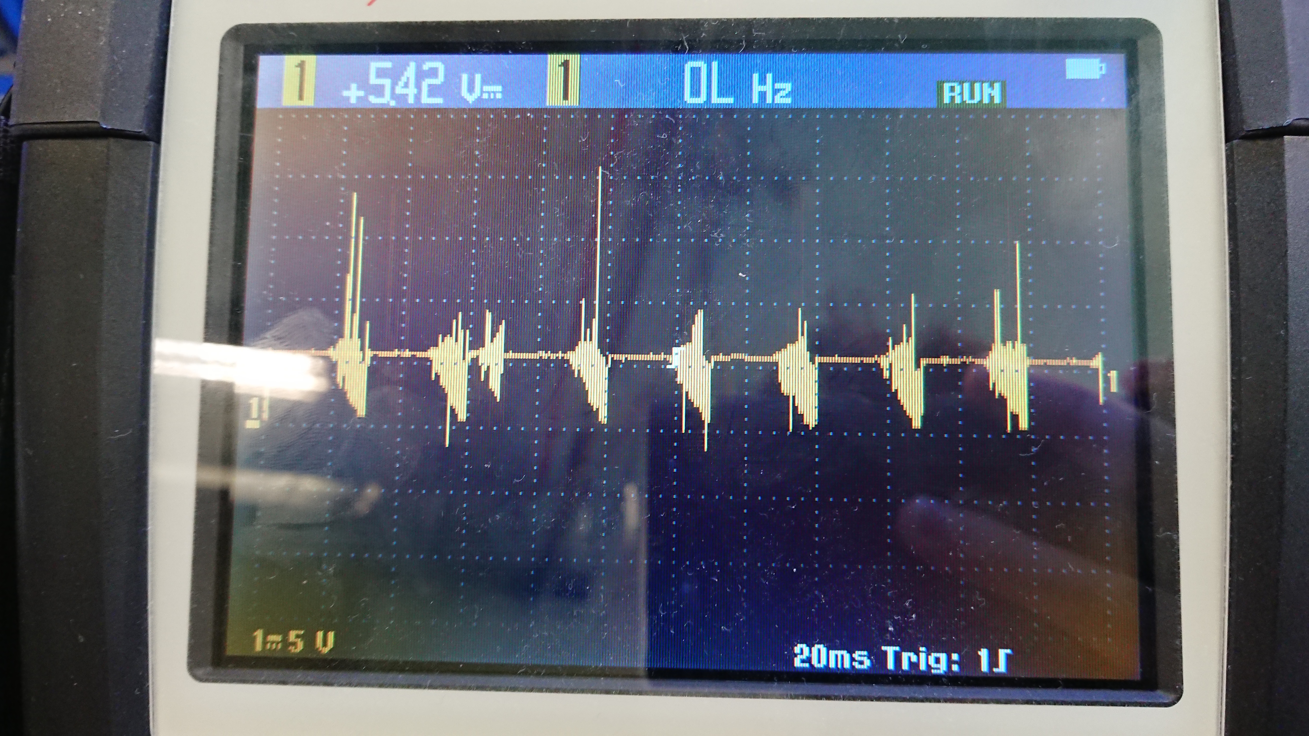
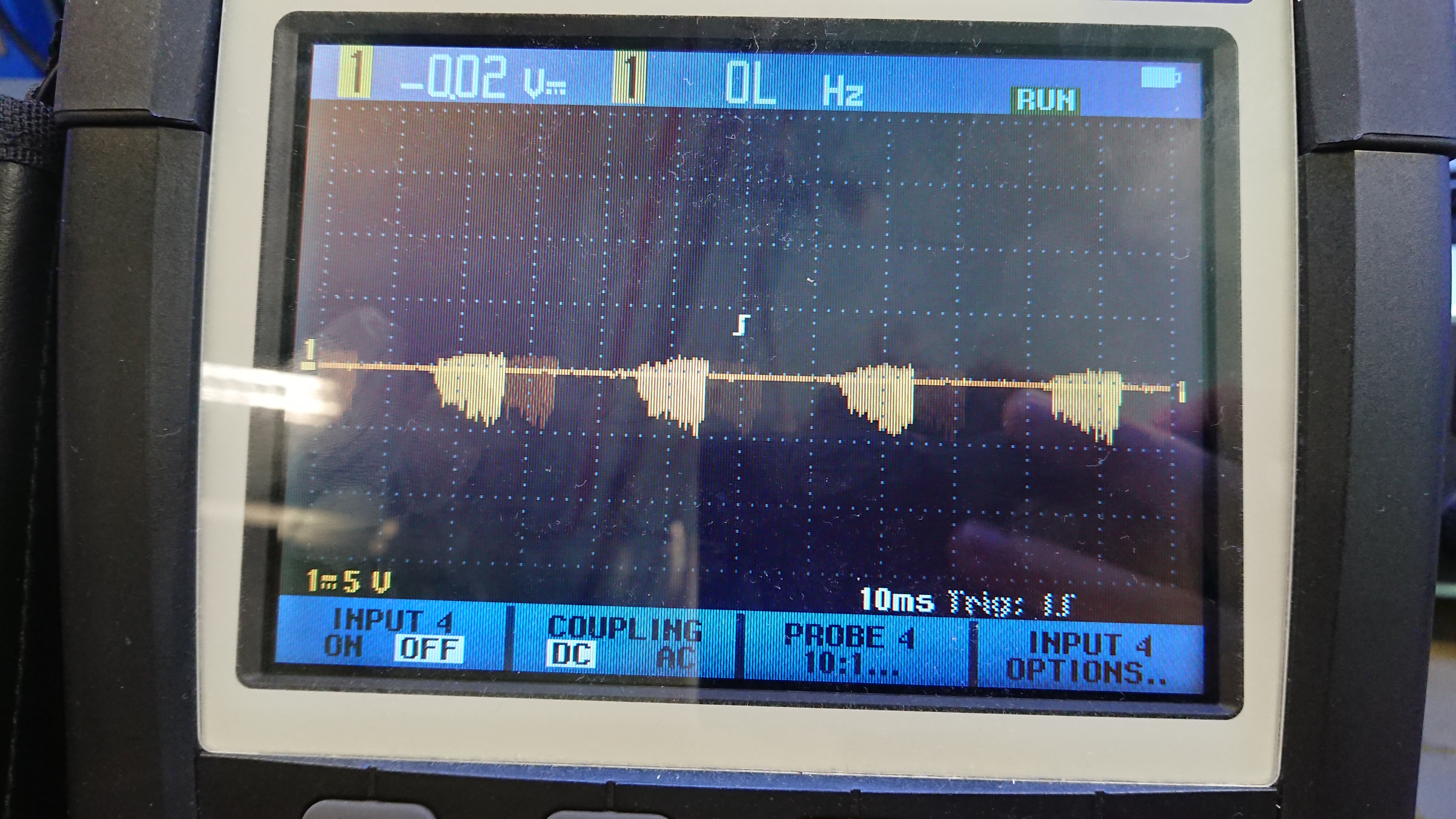
And I get this out after the diodes (note the Vmax):
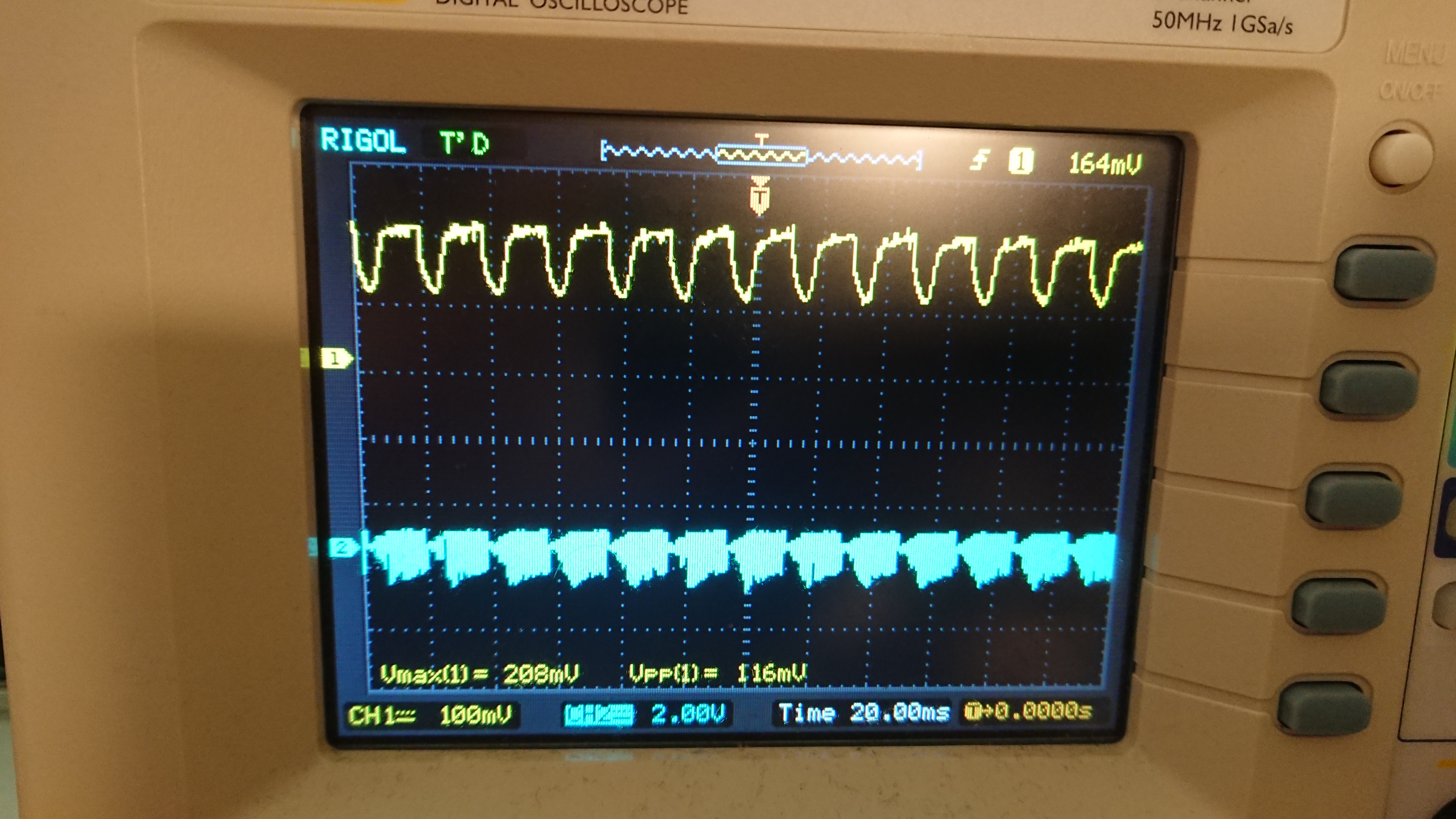
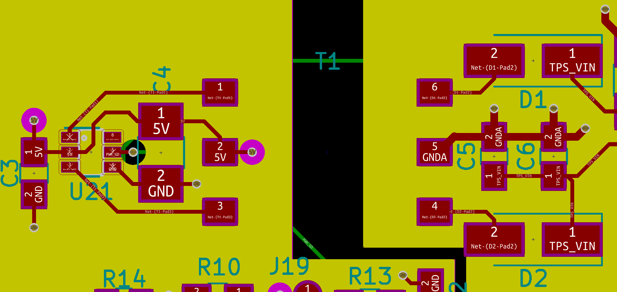
I suspect something in my implementation is fundamentally wrong, and given this is my first work with transformers I wouldn't be surprised. Here is the schematic of my PCB, the components after the 5VA output of the TPS61175 are not fitted to the PCB currently, so the regulator is unloaded:
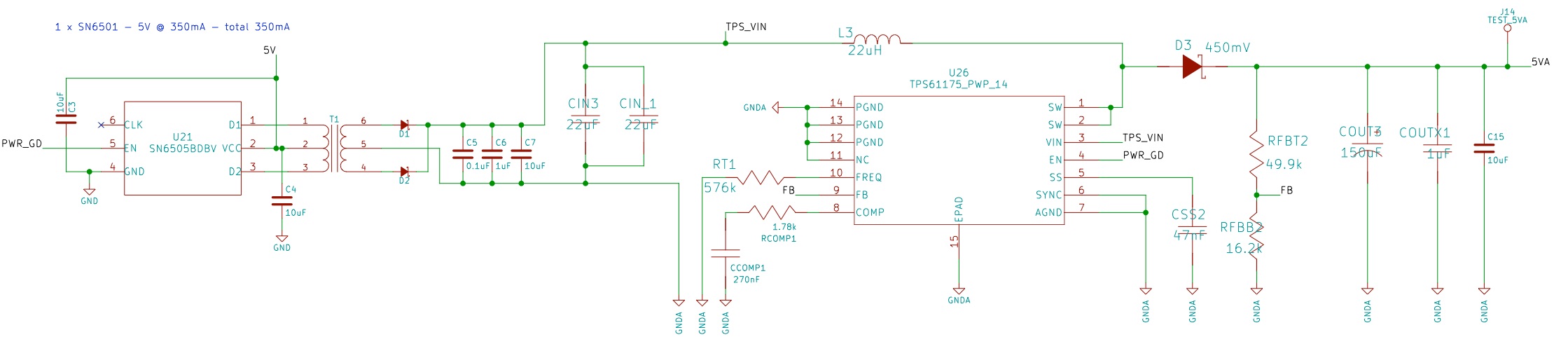
That's a lot of information, so thank you for taking the time to read. My main question is; can you see any mistakes in my implementation that could lead to a much lower power output across the transformer? If anyone has any suggestions as to design best-practices or any gut reactions that they think could be the cause, that aren't necessarily substantiated by the evidence, I'd be happy to investigate them - I am totally stuck!
Thanks in advance,
Louis