


Other Parts Discussed in Thread: TPS2421-2
When I transition down from any voltage to any voltage, it all works great, except the +15V -> +5V.
When transitioning DOWN from one voltage to another, the TPS25740B turns ON a discharge/bleed resistor in order to help the VBUS come down. Once it gets close to the target voltage, it turns OFF and the Buck SMPS regulator takes over.
What I'm seeing is that the +15V -> +5V transition hangs up around 6V to 8V (it's not consistent). Since it doesn't get near +5V, the voltage transition timer expires, and puts the system in "reset".
The signals below are: YEL = VBUS, GRN = Discharge pin 24 (Rdscg = 68 Ohms), BLU = SMPS switching node (other side of the inductor from VPWR)
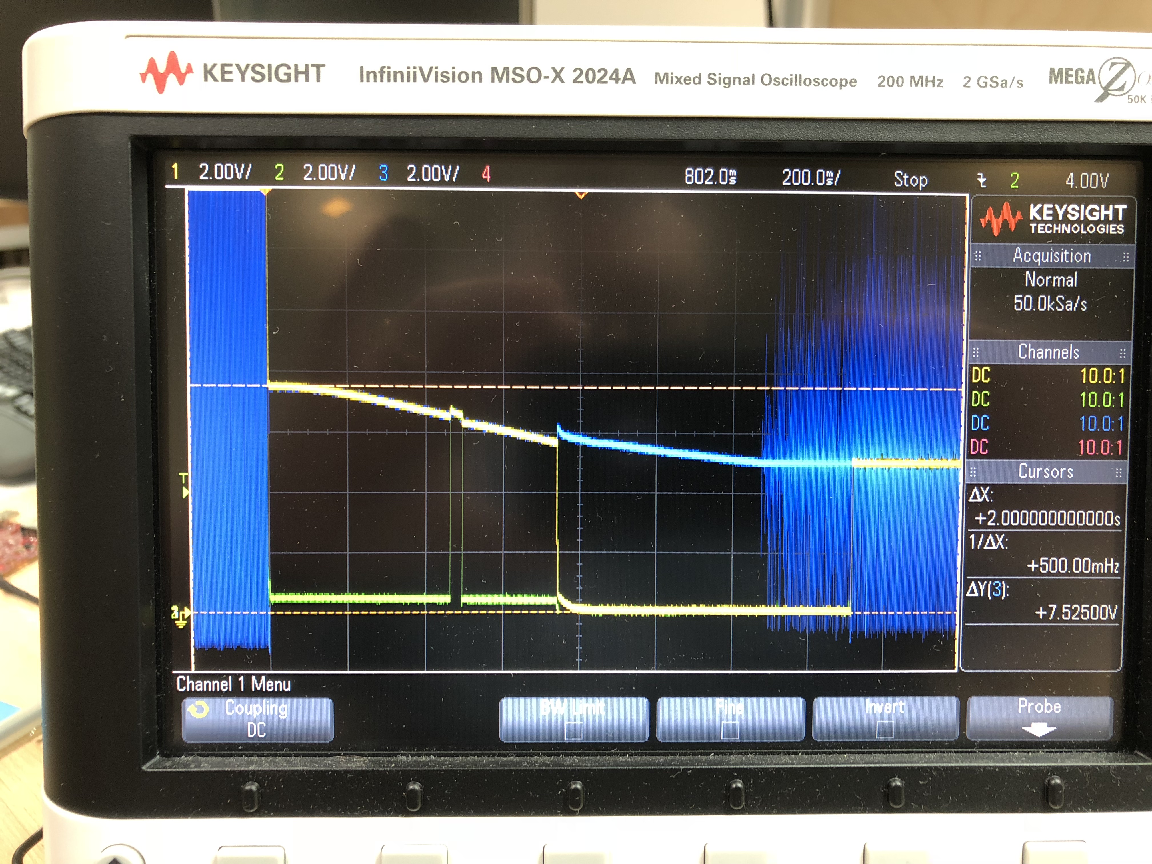
I measured the SMPS switching node. The SMPS is OFF during this transition DOWN, so it's not regulating any energy into the VBUS output. It's also interesting to see that when the discharge is removed, the voltage "recovers" a bit as though there is some IR drop effect going on. Also, once the system goes into "reset", the pass FETs are turned OFF, and VBUS drops quickly to 0V. However, the DC voltage on the other side of the inductor continues to decay, only with some kind of IR "bump". This implies that the source of the "phantom power" is on the VPWR side of the FETs, not the VBUS.
I also reduced the discharge resistor value to about half (from 120 Ohms -> 68 Ohms). All the other transitions happen faster, but this one remains unchanged.
Again, what is strange is that the transition from +20V -> +5V and +9V -> +5V doesn't do this, and the transition from +15V -> +9V works just fine!

