This thread has been locked.

If you have a related question, please click the "Ask a related question" button in the top right corner. The newly created question will be automatically linked to this question.

TPD4E004: TPD4E004DRYR

Part Number: TPD4E004

Hi,

As per datasheet of "TPD4E004DRYR", Channel Input capacitance is given as 1.6pF typical and 2pF Max.

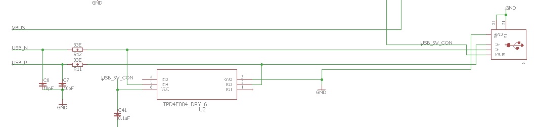
On one of the circuit we have C8 and C7 as 10pF each as seen in attached image.

Are C8 and C7 Channel input capacitance?

If yes, then Is the value of 10pF feasible or should we change as per datasheet.?

Any link to app note on how to calculate C8, C7, R12 and R11 for "usb2.0 esd protection" will be of great help.

Thanks in Advance.

Regards,

Rahul

  • Hello,

    Having a 10pF capacitance on the line is too high for USB2.0 signal.

    Why do you need C7 and C8 R11 and R12? Are you trying to filter out noise? Most of the time people will put in common mode chokes on the data lines to filter out common mode noise if need be. Otherwise the ESD is going to do the protection