This thread has been locked.
If you have a related question, please click the "Ask a related question" button in the top right corner. The newly created question will be automatically linked to this question.
Part Number: ISO5500
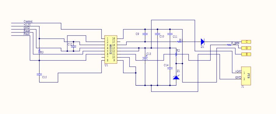
Hello everyone. I am developing a 3kw solar inverter circuit. Currently, I am using ISO5500 to drive IGBT and I have also developed a DC/DC isolated supply using UC3845 with output +15/-8v and .5A for the gate drive supply . The problem is that whenever I connect this dc/dc supply and run my circuit ISO5500 starts producing faults and my system shuts down and when I replace this supply with 15V step-down transformer then I face no such issue the ISO5500 works fine without generating any fault signal. I need help in identifying why ISO5500 is generating a fault signal. Do I need to take any protective measure regarding spurious faults or if the problem is in the Isolated power supply then how to design it correctly for the gate drive application.
Best regards and thanks in advance.
I have attached the schematics of the gate driver and the power supply.
I have followed the recommended circuit in case of the power supply as provided in the datasheet. The Ic I have used is UC3843.
In the Driver circuit, I have used a zener(Z1) and resistor(R2) combination to generate a -ve voltage of - 8v. Other than that I followed the recommended circuit
As I only have 1 two channel oscilloscope, I am unable to provide you with the scope captures of so many signals altogether.
I have some doubts-
1. Can fault signal be only generated if Desat pin detects a voltage rise above a certain level? .Can some noise on the input side affect the fault signal sensing via the microcontroller? What can be the other possible reasons if the microcontroller is detecting a Low State on the fault pin?.
2. Can UC3843 based Switching power supply act as a source for the gate driver input if designed properly?. If not then what can be the other options that i can look into for the driver supply. I am taking the input for the UC3843 based power supply from solar panel string, voltage is ranging from 150-350V.
Regards
Archit
Hi Archit,
Thanks for the information. The schematic looks fine to me.
1. As designed, the /FAULT signal should go low when the voltage on DESAT pin goes above the threshold value. However, external noises may also corrupt the signal on the /FAULT pin. Have you added a 3.3k pull up resistor on the /FAULT pin as recommended. Also, what is the output state when the /FAULT goes to low? In order for us to better understand the situation, please measure the power supply voltages, DESAT pin voltage, and PWM input signal.
2. UC3843 based design is able to provide the right power supplies to ISO5500 if designed properly.
With Regards,
Xiong