This thread has been locked.

If you have a related question, please click the "Ask a related question" button in the top right corner. The newly created question will be automatically linked to this question.

TLK1102E: TLK1102E

Part Number: TLK1102E
Other Parts Discussed in Thread: DS100BR111, DS125BR111

Hi 

We are using the TLK1102E we are looking for some more details :

  • The trace length from the TLK1102E to the connector ? there is only details about cable length 
  • Is there any guide for registers setting ?
  • Is there an IBIS model ?

regards,

Avi Amitai

  • Hi Avi,

    The graphic you are describing sounds like the diagram on the datasheet first page.  This diagram is based on an active cable design and the TLK1102E was placed on the cable assembly paddlecard.  There was approximately 1 inch of trace to the bulk cable and 1 inch of trace to the SFP+ connector.

    I only have the datasheet as a guide to setting the registers.

    I do not have a model for this device.

    There are several alternate products for this device that support IBIS-AMI modeling and have EVMs available.

    DS125BR111 and DS100BR111

    Regards,

    Lee

  • Hello Lee,

    I'm Eli, a colleague of Avi from OSR Enterprises,

    Thank you for the answer,

    In fact, there are a few specific questions about the input bandwidth adjastment and other features of the component:

    Our transmit rate is 10Gbps, and we could see that the max input bandwidth is 11GHz. According to this number it could hardly pass the second harmonic of the transmitted signal (the first harminic must be 5GHz), and it looks as not enough for the proper reconstruction of the signal. Am I missing something? Could you please explain it to me? 

    And the second question about the bandwidth: there is 4 bit (16 levels) of configuration of the bandwidth, but, unfortunately, the data sheet doesn't tell us about what are the step of each frequency level. Is it just uniform step between 4.5 to 11 GHz (11-4.5)/16 = 400 MHz? any other distribution/step?

    Additional question about offset cancellation: since our input signals are AC coupled, are there any reason to have the offset cancellation ON? When it is recommended to turn the offset cancellation OFF?

    Thanks,

    Eli

  • Eli,

    The equalizer is designed for a peak voltage gain at the Nyquist frequency of the data.  Bandwidth beyond what is specified in the equalizer does not help to equalize the incoming signal.  This is typical of all linear equalizers, excessive bandwidth and gain in these circuits would actually increase the noise level within the waveform and decrease the performance.

    If there is a 10 Gbps or higher datarate we recommend the maximum bandwidth.  At lower datrates like 5 Gbps the added noise is not usually as critical and the maximum bandwidth default setting works well.  The adjustment in bandwidth setting is relatively linear by design.

    Some applications my benefit from offset cancelation (input signal dependent).  We have been able to turn off the input offset cancellation using lab generators, but within a real system and non-ideal drivers, there is some benefit to retain the input offset cancellation function.

    Regards,

    Lee


  • Hi Lee,

    You wrote that the "equalizer is designed for  for a peak voltage gain at the Nyquist frequency of the data". For my understanding, the Nyquist frequency of the data has to include at least 3rd harmonics of the signal, which for the signal of 10Gbps stands at 5x3=15 GHz. But when the input bandwidth filter is just 11 GHz, it covers only 1st and 2nd harmonics (the 2nd is generally neglected). Isn't it correct?

    Thanks,

    Eli

  • Hi Eli,

    The Nyquist of a PRBS signal is the maximum frequency of the data.  For a 10 Gbps signal the Nyquist is 10 GHz, most pure linear equalizers for NRZ signaling are built to have maximum gain at or just beyond this value to optimize compensation of the signal from attenuation in the signal path.

    The signal timing can be completely reconstructed without having bandwidth extend beyond the 3rd harmonic.  If you are looking at an oscilloscope, then the higher harmonics are very important.

    Regards,

    Lee

  • Hi Lee,

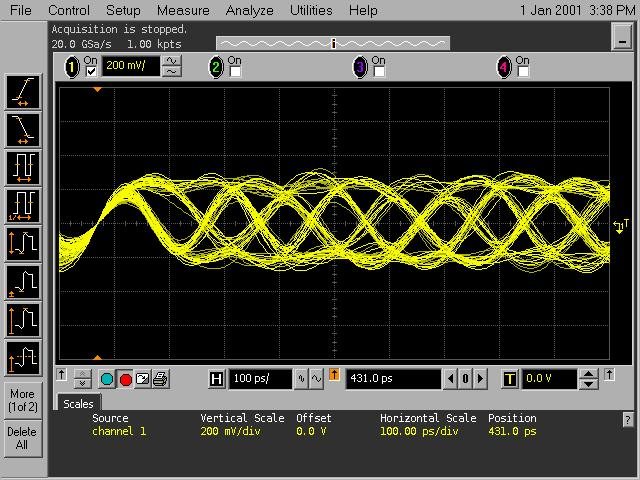
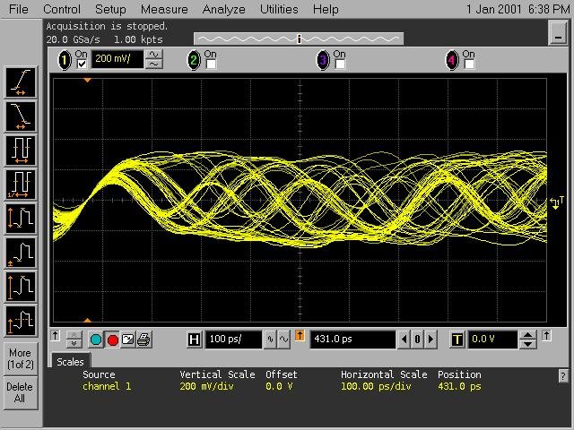
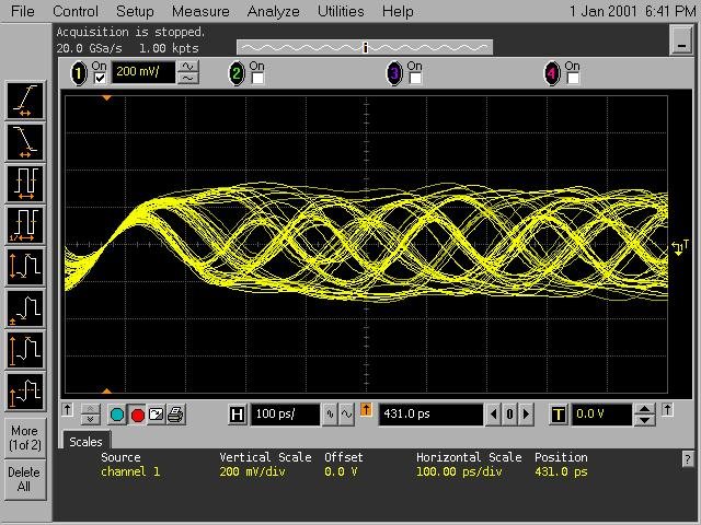
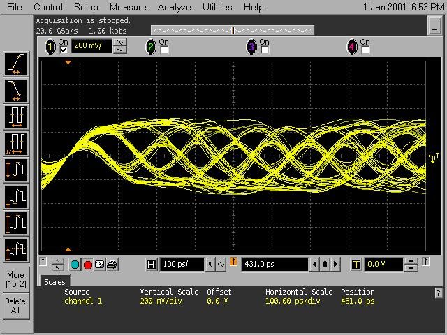
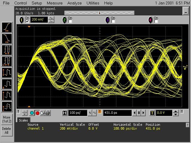
    in contnue to this session, please see attached picture from scope representing the input signal to the TLK1102E (in our board), and the output of the TLK (also in our board).

    the input to the TLK was measured on the TLK input pins, the output from the TLK was measured on the QSFP module pins.

    you can see that the input is in relatevly good eye opening, but the output, regardless the configuration, seems very bad.

    in our board, the way from the TLK device to the QSFP+ module is about 4", all traces are diff 100R on P.S. one via on each signal (from P.S to C.S).

    Please advise how this can happen?

    what should we configure to make the output better?

    input to the device:

    output, on QSFP, BW=5:

    output, on QSFP, BW=full:

    output, on QSFP, BW=full Eq=a amp=5:

    output, on QSFP, BW=5 Eq=a amp=full:

    please advise,

    Ron.

  • Hi Ron,

    Thanks for showing all of the data.  Given that the input signal looks relatively low loss, I would take the best waveform you have now and apply some de-emphasis to the output.  There is likely 4-5 dB of loss in the traces between the TLK output and the QSFP interface.

    Regards,

    Lee