This thread has been locked.
If you have a related question, please click the "Ask a related question" button in the top right corner. The newly created question will be automatically linked to this question.
Team,
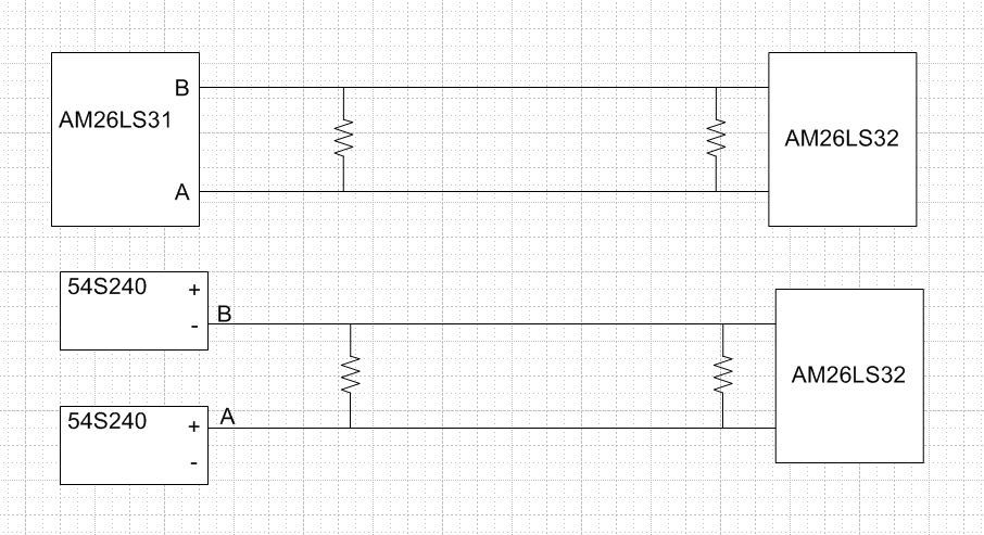
Two manufacturers made a subassembly I am testing. One used the correct 26ls31 driver, and the other used two 54S240 inverters (one input is inverted by 54LS04). The subassembly that receives this circuit has a 26LS32DM , with 6.8 to 9k input resistance (calculated or inferred from other tests). I am told this correctly generates the expected outputs for both manufacturers at the box and system level. I used the AM26LS32 in test receiving circuit, which has input resistance of 12 to 15K. It only passes the manufacturer that used the 26ls31 driver.
Page 15 has the equivalent circuit for AM26LS32AC. http://www.ti.com/lit/ds/symlink/am26ls32ac.pdf
The test circuit has the normal 1k serial terminations, which can be removed easily. The 26ls31 or 54S240 do not have any serial termination resistors in their respective subassemblies. Is getting an IC with the lower input resistance the only option? Is there an issue with PCB footprint dimensions between the commercial AM26LS32 and the mil qualified parts with the lower input resistance?
Thank you.
no parallel terminations
Manufacturer A subassembly cable Manufacturer C
26LS31 Y output – no serial termination – twisted pair wire1 – 1k ohm serial – 26LS32 A input
26LS31 Z output – no serial termination – twisted pair wire2 – 1k ohm serial – 26LS32 B input
Manufacturer B subassembly cable Manufacturer C
54S240+ – no serial termination – twisted pair wire1 – 1k ohm serial – 26LS32 A input
54S240- – no serial termination – twisted pair wire2 – 1k ohm serial – 26LS32 B input
This apparent doesn't drive correctly, as the software at test masks the digital failure.
Is there a termination scheme that can be added at Manufacturer B or C (1k can be removed)?
Or is the only option to take one 54S240 outputs and use a 26LS31?
Thanks,
Nick
Nick,
Can you elaborate "doesn't drive correctly"? Do you mean the voltage amplitude is too small? Among all the scenario you listed, which ones work and which ones don't? If you use AM26LS31 as the driver and AM26LS32 as the receiver, the expected voltage is larger than 1.5V with 120 termination resistors on both sides (per RS-485 standard). Without termination, the voltage level would go up. I'm not familiar with 54S240's driving capability. Do you have any comparison results between AM26LS31 and 54S240?
Regards,
Hao
Hao,
I don't have the ability to measure when the two subassemblies are together.
I'll just have to come up with a separate harness for test setup that will verify the single ended logic of the 54S240.
Brad Davis or Steve Widener,
Can you close the question?
Thanks,
Nick